Update: LED Reading Lamp Materializing
For those of you with short attention spans, like me, here is a quick and lame video I threw together in iMovie:
I am building this for the new awesome bed I will be building this winter for our bedroom. There will be two of these lamps, one for me and one for my wife on either side of the headboard. The LED head will have a metal (or whatever I end up finding) shroud on it to keep light pollution down to a dull roar for the other person who might be sleeping.
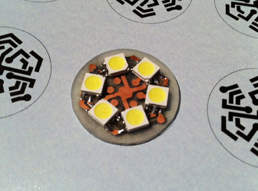
The previous post showed the traces for the printed circuit board I made. Here is a photo of the board with the six surface-mount triple-LED packages soldered into place:
Each of those white squares has three über-bright white LEDs in the yellow stuff. I designed the circuit board to connect one LED from each of three SMD packages at a time, thinking I might use that layout to better dim the whole lamp head. Turns out, that circuit layout just makes for a really cool-looking circuit board.
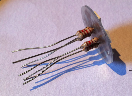
Here is a photo of the underside of the LED lamp head with the resistors for each set of three LEDs in series:
There are three holes left, as of that photo, which will have the ground wire connected through and soldered. Each set of three LEDs and their resistor will have 12 volts supplied to them which will be controlled by a 3904 PNP transistor which itself will be controlled by the AVR microcontroller. The transistor will act as a switch for the pulse-width modulation provided by the microcontroller.
For those who aren't sure what pulse-width modulation is, the short story is that it is super-fast on and off switching. It's fast enough that you do not see a flicker. We use PWM to dim LEDs because they do not work efficiently without a specific voltage being given to them. So, we flicker the voltage that the LED likes really fast and emulate dimming. For each "flicker" of the switch, the amount of time that flicker lasts can be divided between on and off. The more on time we give the LED, the brighter it looks. The more off time, the dimmer it looks. Weird, yes. But, that's the right way to do it. PWM also works for DC motors and such. Discussion for another time. Maybe that's a discussion for someone who was properly trained in all this. I know enough to be dangerous, even though I try to be safe at all time.
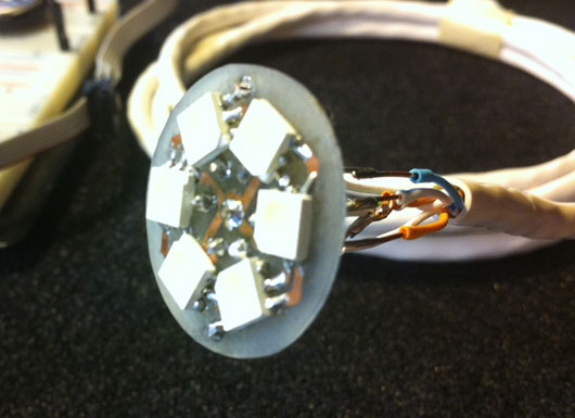
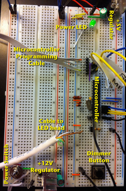
The cable carries six +12VDC wires and two ground wires to the back of the LED lamp head. The other end is currently plugged into the breadboard prototype of the controlling circuit. Here is the breadboard and labels for the various parts:
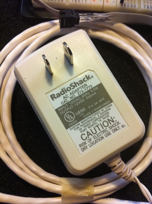
The power for the whole shindig is provided by a spare "wall wart" power supply, like the ones that power your TV boxes or network routers or wireless home telephone base stations. Here is the actual one I'm using, the end of which I snipped off to be able to plug its wires into my breadboard:
These silly things provide pretty craptastic power, as far as DC circuits are concerned. They pretty much always supply a voltage other than what the label reads. This particular one measure out at 15 volts. Voltage to spare, baby! What's important is how much power (amps) we need to draw from the thing. Our circuit cannot pull more milliamps from the adapter than it is labeled to be able to supply. Luckily for this little project, we're only drawing at maximum about 91 milliamps. Not much at all, considering we're powering 18 super-bright LEDs and a little computer-on-a-chip. The Radio Shack adapter I'm using provides up to 500 mA of current. We're good.
The Atmel AVR microcontroller (the model is an ATmega328P, which is complete overkill for this, yes, but I didn't feel like reconfiguring my customized Arduino IDE to work with one of my little 8-pin ATtiny chips) basically sits and waits for the pushbutton to be pressed. When it senses a press, it delays for 25 milliseconds to keep the switch from bouncing on and off (a thing called, "switch bounce"), then gradually fades the LEDs up to the next brightness level. When it hits the last level, the next button press will shut off the LEDs.
Hope you found that one interesting!
