Disney "Glow With The Show" Ears Teardown
On the way to lunch, one day, our CTO told us about this amazing show they put on at Disneyland called, "World of Color" in which all of these special "Glow with the Show" mouse ear hats changed their glowing colors in sync with the show. Of course, the car full of techies and nerds instantly got to speculating on the tech behind it all. 
UPDATE (2012.08.17): I received a linkback from the Disneyland Resort Update website where they had a video of one of the imagineers explaining more about the hats in this YouTube video: http://youtu.be/TbxkrpWu7hQ
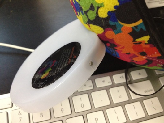
The CTO recently visited Disneyland in California and bought me one of the special "Mickey Ears" hat with RGB LEDs in the ears. They have a little metal touch sensing button to turn them on and off. When on, they rotate through different colors which get diffused in the translucent white plastic ears. Of course, color rotating with RGB LEDs is not-so-advanced and I've done it many times (see the Mood Lamp for my wife).
I'm finished speculating about the tech.
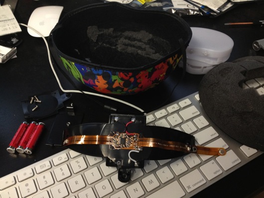
I tore apart the hat. It's nice and simple and elegant. There are a couple of mystery parts, but I think I have a good guess as to their functions. More on those later. Overall, the tech is stuff we DIYers use every day for our own "shows" and props, so that's cool in itself. I'm sure the Imagineers at Disney will eventually explain it all on a higher level, but, for now, I think I got the idea.
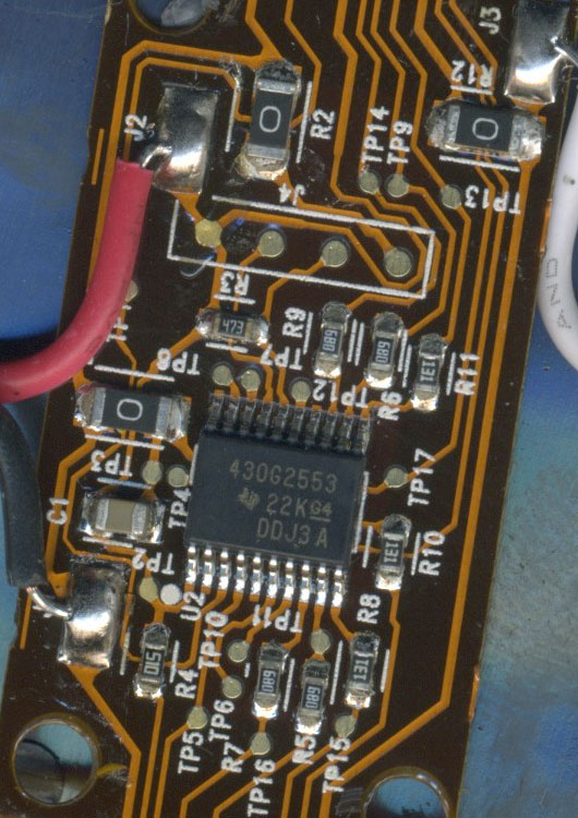
The brain in the hat (aside from the brain of the kid wearing the hat) is a Texas Instruments MSP430G2553 microcontroller. It's in a TSSOP-20 package and is mounted with everything else on a single-sided flexible PCB that runs from one ear, through the top of the hat on a plastic frame and on into the other ear. The three-slot AAA battery pack is built into this frame. The MCU and most parts are powered off of just two of the batteries. They've brought the spy-bi-wire lines out to a little pad of contacts and there are numerous test point marked on the board.
As for normal passive components, there are a handful or resistors and a couple of capacitors. A few of the resistors are simply 0-Ohm jumpers (R1, R2 and R12) to hop over other lines.
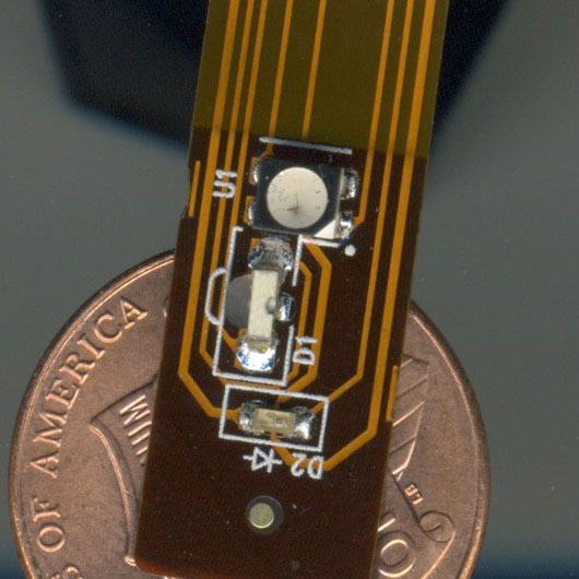
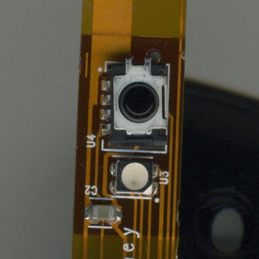
The obvious parts are the two RGB LEDs located in each ear (U1 and U3 [see below]). They work off the full battery power of 4.5V (J3, white wire) and appear to be sinking current through six IO pins on the microcontroller (pins 8, 9, 10 for LED U1 and pins 11, 12 and 13 for LED U3). 4.5V goes into a common anode and each of the individual LED chips in the component are turned on by sinking current through a resistor and then through the IO pin.
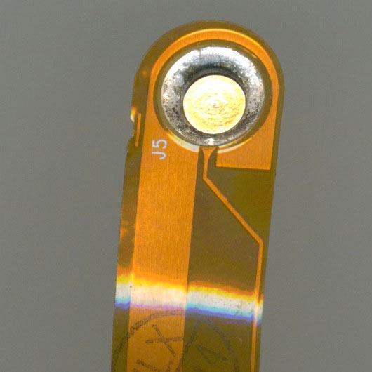
The On/Off switch is a simple piece of metal surrounded by a ground plane and that has a single line running back to an IO pin on the MCU. The is a capacitor (C1) between ground and the sense line. My RadioShack DMM measured about 0.16 nF on both capacitors on the board. Not sure how accurate that is. Hell, I'm not even sure I'm using that feature on my DMM correctly. You get what you pay for with my stuff. ;) It appears from the datasheet that these TI MCUs can have up to 24 touch-sense lines, so I'm guessing they're utilizing one line for touch, since only other part used in that part of the circuit is that C1 cap.
There is what I believe to be a Vishay TSMP6000 IR receiver (U4) in one ear. What the pins are connected to matches the pinouts for that part from the datasheet. The images in the datasheet match the part visually, as far as I could tell. So, to be sure I guessed correctly, I grabbed my Samsung flat panel TV remote and my oscilloscope and checked it out. I hooked up the ground clip for the scope to the ground wire on the battery pack and clipped the probe to pin 4 of the receiver. The scope showed +3V solid. I then clicked various buttons on the remote and POW! I watched the remote's signals clearly on the scope.
There are two other diode-esque parts in the other ear (see the image for the LEDs (U1) above). D1, which has a tiny lens, two leads and faces forward (90°) to the face of the PCB, flashes a bright pulse of IR about once every 5 to 10 seconds or so. I was able to observe this with my Sony TRV20 miniDV (remember those?) camera in "Nightvision" mode. On the oscilloscope, D2 shows a digital signal (+3V on and 0V off). It has a 5 ms wavelength and appears to be on (3V) for 10 ms and off (0V) for 5 ms. It looks like a clear super-tiny LED or photodiode, but I'm not versed enough in all of this stuff to easily recognize it.
I've seen the Vishay IR receiver a number of times before. It's often used in IR signal learning applications (which the datasheet suggests as a possible application), so I could totally see this thing being used to received IR data packets for syncing with the show. It gives a carrier signal out on the output pin and can receive signals from 20 KHz to 60 KHz, according to the datasheet.
I can find no other signs of wireless tech in the hat.
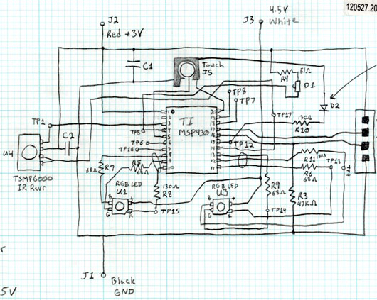
Here is the pencil schematic I drew when I mapped everything out (please forgive the crudeness and slop):
That's it! If I knew more about this stuff than I do, I'd love to offer up more, but that's what you get from this complete amateur. Enjoy!
