A car stereo, some extra car stereo speakers, some hardwood, and a ATX power supply for a computer and SHAZAM! You get a garage stereo that can play your iPod, XM radio, CDs, and AM/FM radio. This project was easy and only a little tedious to make. It was fun and it sounds awesome. Plus, the little speakers I had in my garage cabinet are not the greatest, but they're not bad. With a 500 or 600 watt power supply, I can beef it up someday if I get the energy.
Adjustable Workbench Cigar Holder
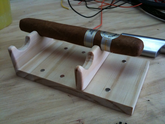
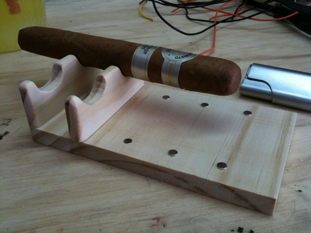
I usually put my burning cigars across the top of a ceramic mug on my workbench when I'm in the garage. The great thing about ceramic is that it's pretty much fireproof. What fun is that? The real problem, though, is that the cigars got short enough toward the end of smoking that they wouldn't fit across the mouth of the mug. So, I built an adjustable holder that IS flammable:

Super easy to build. A couple of pieces that sit veritcal, one that is permanently attached at the end of the base. The other has two magnets in the bottom that are attracted to the sets of magnets stuck into the base. As the cigar gets shorter, you simply slide the movable vertical thingie closer to the fixed one.
Magnets are left over from the casino dice Rubik's cubes I made (see posts coming soon).
I had no plans. I just ran some extra pieces of pine through the band saw and drilled some holes for magnets and used Super Glue Gel to hold them in. Nothing to it. Hopefully, the cigar never burns down to the point where the hot end touches the wood on the holder. :)
Turn a Servo Into an Inexpensive Geared Motor
In my UME Mark II's (UME = "Useless Machine Ever"), originally I would program an Atmel AVR microcontroller to turn an RC servo forward and backward using timed pulses like you're supposed to. But, when you want to build many machines, microcontrollers are not the way to go. Simple polarity-changing circuits are the way to go. But, you still want the RPMs of a servo without the hassle of the pulsing control. So, you hack the servo and make it a geared motor. Easy! Here's how...

Grab yourself one o' them thar RC servos for a good price at your local hobby shop or on-line. They look so innocent. If you listen, they make a whimpering sound because they know that phillips head screwdriver in your hand is there for kicks.
I hope that my lack of knowledge in all that I do is entertaining and not a hinderance in the usefulness of these posts. :) So, that said, look at the above picture. I took off the star-shaped armature thingie.
Unscrew the screws in the bottom of the case of the servo-soon-to-be-geared-motor.
Remove the cover on the bottom of the servo. You'll see nifty circuitry and the spots where the three wires are soldered to the board.
Carefully remove the top of the servo that contains the gears and pins and lubricating goo. I bold the word, "carefully" because you need to put this all back in the way it came out. If you can't get it all back together, you will have a nice pile of gears, pins, circuitry, a plastic case, some wire, and a neato DC motor. Take pictures if these don't cut mustard. They can help back track the destruction and make it reversible.
Shimmy the neato circuitry and motor guts out of the plastic case. The potentiometer (black thing standing on thick leads opposite the motor) is used by the circuitry to indicate where the shaft is positioned at any given moment. Once the hack is complete, it will be unused. I'll give you some options for it later on.
I used my ACMG robot (aligator clip magnifying glass) to hold the guts while I worked. Desolder the three wires from the board. Remember not to heat the stuff you work on with the soldering iron for too long. That heat can travel to components that don't like warm weather and can cause severe rash or sunburn or death.
Solder the red and black wires to the motor leads. Once you do this, the servo is simply an inexpensive geared motor. The robot makes this very easy to do. You can use a wife, girlfriend, son, daughter, or even an uncle to hold the work, but they're nowhere near as steady as a the alligator clips.
Wires soldered. Route them between the pokey little component leads sticking out of the bottom of the neato circuit board because there isn't much room between the PCB and the case cover and the wires have to travel across the board to the hole in the case. I like the path I chose. It looks like a... Well, it doesn't look like anything, but you can pretend.
View of the servo... Er, almost-a-geared-motor (now) looking at the underside of the top of the servo (with the gears) and the top of the main body (at right). The bearings on the black gear are tiny and cool. That black gear has a little nub on it that acts as a stop at one of two positions 180 degrees from each other in the rotation of that shaft. We need that snipped off and trimmed.
See the nub? It's what I'm holding onto with the wire cutters. You need to trim that down flush with the shaft and with the face of the gear (the part of the gear parallel to the back side of the wire cutters in this photo). That will prevent the gear from stopping against the stops that are built into the case of the servo.
Look on the right side of the gear, just below the bearings on the rear of the face of the gear. Make sure there are not bits left behind or you will hear clicking as those remnants click past the stops in the gear box. I suppose you could clip the stops, as well. But, you can see in this photo that I have a little bit of trimming to do, yet.
Use your new geared motor as you wish. I learned to circumvent the circuitry on these from various posts on the IntarWebs. It's not hard at all. If you screw up, the servos I found locally at the hobby shop were only about $12, so it isn't the end of the world if you fubar one. In the photo above, you can see the unfinished tops and "robotic arms" from one of the Useless Machines (see post on my site about this device).
Cigar Coolidor (Wine Cooler + Humidor = Coolidor)
This is one of the first "major" projects I built that involved electricity and electronics. This project makes it super-simple for me to manage my expensive (for me) cigar collection with minimal effort. It uses a 6-bottle wine fridge, some custom-cut Spanish cedar, and a Cigar Oasis XL electronic humidor humidifier.

The fridge was about $99 on-line (I may have gotten it at Wal-mart's website, I can't remember). The Cigar Oasis was about $90 on-line. The Spanish cedar was the expensive part. I think I spent about $160 for a 6' piece of uncut and unfinished wood. I had to have the people at Woodworker's Source (Phoenix area, near my home) rip the big plank down to nice and thin planks with which I could line the fridge. The cutting part was about as much as the plank of cedar.
I kinda rushed this project, as you can see. The shelves are not completely level and don't fit perfectly. Most of my time was spent measuring and shaping the pieces so that they would fit without needing glue or fasteners. It turned out well enough to do the job.
The electronics weren't too tough. It was my first project that involved busting open a device that used wall power. That was unnerving. But, it isn't rocket science. I just opened up the back of the fridge, found where the power supply fed the electronics of the fridge at ~5V and tapped the power cord of the Cigar Oasis into that line. The Cigar Oasis doesn't draw a lot of power, so it seemed the power supply wouldn't mind. Er, at least, in the two or three years it's been running in my Man Cave™, it hasn't quit or caught fire. ;)
Like I just said, it's been running for about two or three years and I've filled the Cigar Oasis maybe twice. Other than that, I haven't touched the humidor for maintenance, only to select cigars to enjoy. The fridge keeps the temperature at 70 degrees fahrenheit and the Cigar Oasis keeps the humidity inside the fridge at about 70%.
The photo above is the coolidor after about two or three years. I've loaded and unloaded lots o' cigars. The little readouts on the Cigar Oasis and the little electronic hygrometer don't ever match. The cigars smoke perfectly, so the "63%" showing on the gadget there is low because, when you open a humidor in Arizona, the humidity escapes rapidly... Because we're in a desert. But, when it reads about 65% upwards to %68, the cigars are happiest in my experience. To get the optimum humidity, I have to keep the Oasis set at about 68%.
This project is easy to do. If you're a cigar geek, I highly recommend taking a little time to build a humidor that can manage itself. Set and forget. It's awesome.
Sharp Clock (Saw Blade Recycling)
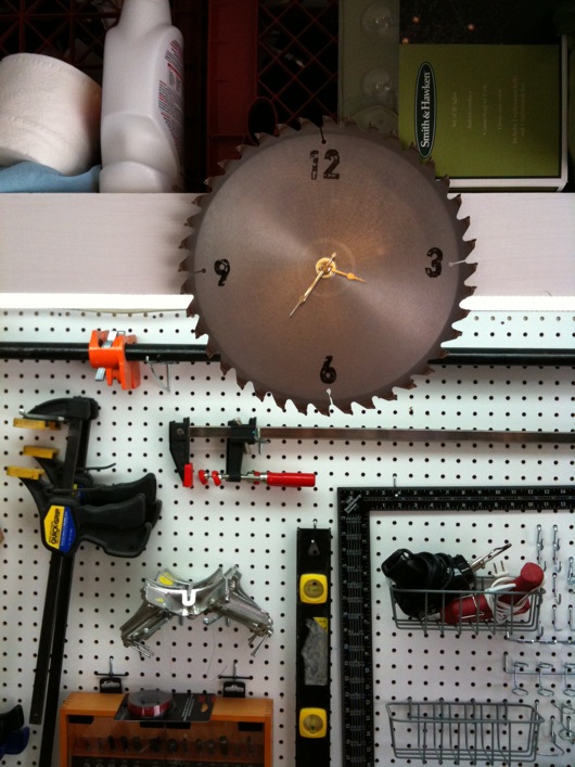
Run down to your local craft or hobby store and grab a $7 quartz clock movement thing. Sand the crap out of the face of an old saw blade. Get a permanent ink pad (I used black and some squishy clear stamp things) and stamp the numbers on the face. Hang it in your workshop or garage.
I bought the clock with a 1/4" stem (or whatever they call it) (the thing that sticks out of the face of your clock to which the clock arms are connected) from Michaels. There are different depths. This was the least of all of them. Saw blades are not thick.
I sanded the heck out of the face of the saw blade. Got it as clean and "brushed" as possible. This, I would think, allows the ink to "soak" into the brushiness of the metal and stick a little better. At least, it probably wears better.
I bought a Staz On Jet Black permanent ink ink pad, a set of Inkadinkado clear acrylic stamp pads, and a set of Recollections Clear Stamps in a font that seemed garagy/workshoppy. Then, I simply inked up the characters I had stuck on the acrylic stamper things and pressed the numbers onto the face of the saw blade.
The clock movement didn't quite fill the hole in the center of the blade, so I used a washer big enough to cover the reminder of the opening that the clock movement stem did not fill. I then tightened the movement down to the washer and the blade.
All you have to do after that is hang it. Make sure you put a sturdy screw into the wall or, in my case, the pine shelving. Saw blades are a little heavy. How do you explain the 10" saw blade clock lodged in your skull to your wife when you need a ride to the hospital? Exactly.
Office Chairiot™ First Run a Success!
 The Office Chairiot™ is a project I've been designing and building since last summer. The Office Chairiot™ is a battery-powered office chair towing device built with custom steel work and motorized scooter parts purchased on-line. With the amazing welding skizillz of the father of one of the owner's of the company where I work, my dream of a modular powered office chair came to fruition recently.
The real first run of the Office Chairiot™ was a week ago or so. There were a few hiccups, but with a little on-site tweaking, it ran well considering it was the first time since the design-on-paper stage that it was fired up for realz. Thanks, Mike(s)!
The steel frame was reworked a little from the first run and arrived last night. It was late and time was short. Sadly, due to a wiring... Due to owner stupidity and some crossed wires, the test drive last night was postponed until this morning. Thankfully, the reversed wiring didn't result in a SECOND lost speed controller. There were no hisses or pops, as we were incredibly careful while testing the connections. Once I actually followed my diagrams, I realized we'd simply hooked it up incorrectly.
So, this morning, I reconnected everything properly, labeled the wire harnesses with my snazzy P-touch labeler, and made the first successful run of the Office Chairiot™ around the mostly empty office. It was clear that having power run to both tires simultaneously is a good thing. It is far better than torque on just one wheel, of course.
I donned my University of Michigan throwback football helmet and some costume old-style motorcycle goggles and piloted the Office Chairiot™ around the office. I was careful at first. I made a couple of runs at high speed (for an office chair, anyway) down the longer corridors of the office space. It was AWESOME! It's not skydiving, but it's not bad for a day at the office.
I'll post photos taken from the inaugural run soon. There were a few photographers on-hand, thankfully. Here is the first clean video from one of the runs with "cling-ons" aboard:
Build photos and design stuff forthcoming.


