It's been a little while since I posted an update on the latest version of the Office Chairiot motorized office chair (the, "Mark II"). I usually add little pieces of updates to the project site for it on Local Motors' personal project website, since I plan on utilizing their facilities to push it to 11.
embedXcode: A Better Way to Develop for Arduino on the Mac using Xcode
If you are writing code for your Arduino on a Mac and you've previously written code using Apple's FREE Xcode IDE, you know that the standard Arduino development environment is lacking in functionality, especially those which professional software developers have had in their IDEs for years. My personal favorite is Apple's Xcode IDE, which is the primary IDE used in developing applications for the OS X on the Mac and for iOS applications on Apple's mobile platforms (which are technically ALSO running Apple's OS X operating system). Find out how easy it is to use a professional-grade IDE to do your Arduino code using embedXcode from Rei Vilo Hobbies.
Introducing: The Office Chairiot Mark II - Labor In Motion Again
What is electric, goes somewhere between 15 and 20 miles per hour and has an Ikea chair on it?
The Office Chairiot Mark II is the second generation of motorized office chair brought to you by yours truly. Why motorize an office chair? That's a silly question and I will not dignify it with an answer. Office chairs are boring. Plus, on a hot summer day, I walk too slowly between our office buildings in ARIZONA. The Office Chairiot Mark II can do it in a fraction of the time and I sweat far less driving it.
How To Compete in Your Company's FitBit Walk Competition While Injured
I built a machine to walk my FitBit for me. I call it the FitBit Cheat-O-Matic! Why? Our office is having a FitBit competition this month (November 2013). In preparing for the competition I overworked my Achilles tendon and could not participate. So, I adopted the mantra:
If you can't join 'em, beat 'em.
The FitBit Cheat-O-Matic is a machine that shakes my FitBit for me 24 hours a day, 7 days a week and does it faster than my normal walking pace. I suppose it's actually faster than most people can run, for that matter. Sure it's cheating! Not only is it cheating, but it's cheating at a level that's so blatant it can't be mistaken for anything else! It's fully disqualified from the competition, of course. But the point is no longer to win the competition, but to be totally ridiculous and to rack up outrageous FitBit stats and make people laugh or maybe shake their heads.
iPotti #2: After a Number One, We Had to Make a Number Two
iPotti #2 is the latest incarnation of iPotti, the custom bathroom availability monitoring system I built for my employer, meltmedia. I started designing and building the original iPotti in 2010 and it went into operation in early 2011. At the time, there wasn't anything like it that we were aware of. Lately, some other similar systems have popped up and their inventors have done some pretty cool stuff with them. I've found inspiration to reinvent iPotti. Plus, at meltmedia we'd like to use the device for marketing purposes in the near future.
Since 2011, meltmedia has outgrown its original office where iPotti ("number one") is installed. At that time there were about 20-some-odd meltmedians. Today, there are over 60 of us and we now occupy TWO different office spaces on the same campus. On the plus side, with the growth in the number of meltmedians came a growth in the number of pottis at meltmedia to service those meltmedians. On the not-plus side, there is only ONE iPotti #1 and it only watches TWO of the 9 or 10 pottis across two buildings. This situation needed to be rectumfied. [snicker]
Charlieplexing LEDs with an AVR ATmega328
How many times has this happened to you? You have a little LED project with an AVR ATmega328 microcontroller (or Arduino) at its core and you need to light up a boatload.... A dingyload of LEDs. Maybe it doesn't happen a lot to you. It's happened on three recent projects for me. My latest two LED projects are a timekeeping piece that illuminates 21 characters from behind and a simple LED chaser thing.
As usual I wanted to keep the component count down on these projects. I also tend to prefer not to use a ton of ICs with busses between them and whatnot, if I can help it. So much darn soldering and stuff. Meh. Luckily, back in 1995, so the Wikipedia story goes, a super-smart dood named Charlie Allen at Maxim Integrated devised a super-ingenius way to control a large number of LEDs using a not-so-large number of microcontroller pins. The method is called, "Charlieplexing" and it seems a but daunting, at first, but it's not that bad once you figger it out.
Making Mad Props for meltmedia's Interactive Superhero Marketing Launch: The HAT
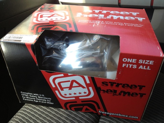
This is the second in a series of three posts that talk about the props I built for my company's internal marketing plan launch for the employees (see previous post for back story). This particular post is about the HAT (Helmet for Accentuating Telepathy) and is our managing partner Justin's Interactive Superhero tool of choice. It allows his Techno Telepathy to reach farther than it would otherwise with the flick of a switch. The blinking LED on the end of the highly tuned antenna tells him his Techno Telepathy is sensing with ludicrous sensitivity. Er, something along those lines. The HAT started life as a simple chrome (plastic that looked like chrome) skateboarding helmet, which means you, too can build a HAT for accentuating your telepathy (if you imagine REALLY hard):
The main purpose of the HAT is to make Justin, one of meltmedia's partners, look like a dingbat (the plunger helps a little, as well):
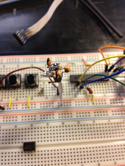
The next thing to do was to make a blinky LED circuit. The cheap and easy way is to use a 555 timer IC, a couple of resistors and a couple of of capacitors:
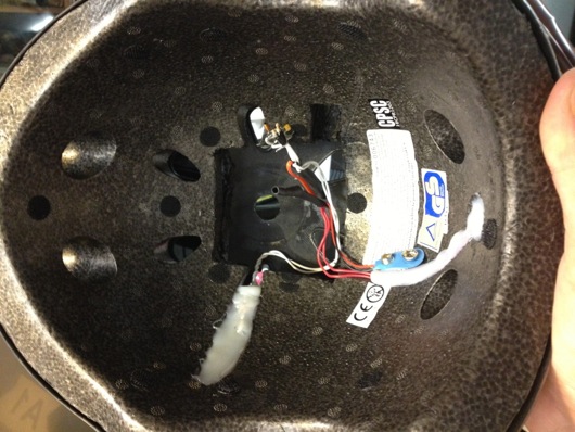
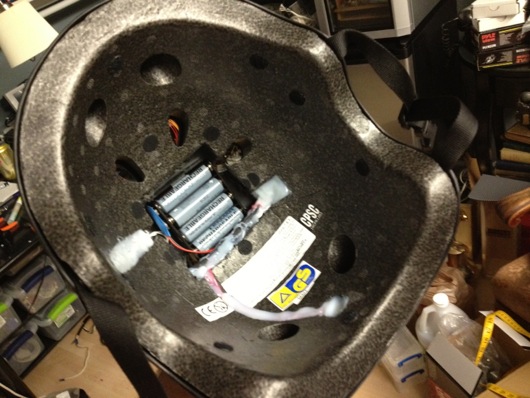
I dead-bugged it to save time and to make it nice and compact, as I wanted to hot-glue it into the foam inside the helmet, like so:
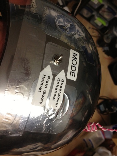
I added a toggle switch to the outside of the helmet to allow Justin to turn off the telepathy accentuation feature and return the helmet to its normal state of being a plain old goofy helmet:
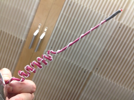
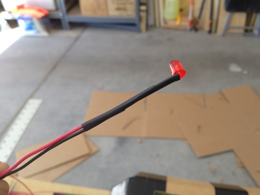
The antenna was a thick piece of electrical wire I had left over from my pool computer upgrade last summer. I wrapped a section of it around a pen, soldered one of the LED leads to it, then wrapped another thinner gauge wire up the thicker wire to provide ground to the LED (it's possible I had the polarity the other way, but you get the idea). I put a little heat-shrink tubing on it to better fixate the LED onto the end of the antenna:
The antenna and most every other thing attached to the helmet was held in place with crap-tonnes (the European measure of a crap-load) of hot glue (sorry for the blurry photo, BTW):
And, finally, a video to show it in action:
Making Mad Props for meltmedia's Interactive Superhero Marketing Launch: Techno HAMMER
I believe I've mentioned it before: I work at an amazing web and software development shop called, "meltmedia." We have a gaggle of highly talented software engineers, web developers and designers. Sometime back in 2011, meltmedia was in search of a new tag line to kick off a for-real live marketing campaign. Marketing was something melt hadn't worried about before then. While in San Francisco at the 2011 Apple World Wide Developer Conference, in a bourbon-fueled barrage of submissions to the company's on-line suggestion box for new company tag lines, I came up with, "We are Interactive Superheroes." It stuck and I won a $90 bottle of bourbon. Woohoo! To be clear, I am fueled by many things: Caffeine, sugar, soda, etc., not just bourbon. I like chocolate milk. I happen to be a major bourbon geek and had been sampling fine bourbons at a speakeasy in San Francisco called, "Bourbon & Branch" before I went back to the hotel and started submitting dozens of mostly silly ideas for meltmedia's new tag line.
For the short attention span version of this, here is a photo of the three partners of meltmedia in their full costumes with their props:
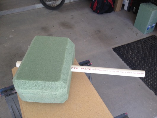
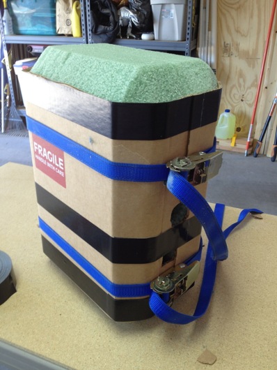
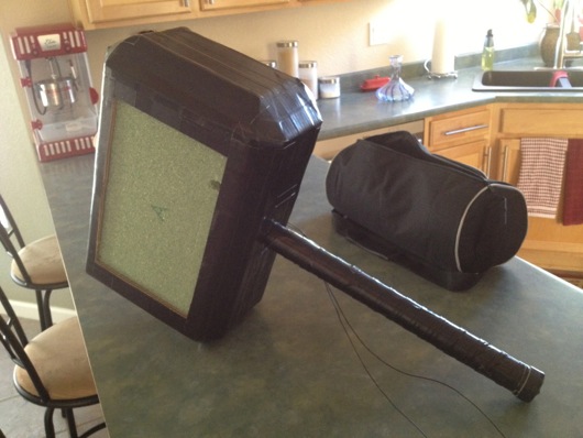
We'll start with the biggest prop: Mike's Techno HAMMER (Highly Active Mike Moulton Energy Repeater). I needed this thing to be big. I didn't have much time for any of these props, especially the HAMMER. To sturdy up the thing and to keep it as lightweight as possible, I started with green foam from Michael's:
The handle is a piece of PVC pipe from my pool equipment upgrade last year. I knew I'd eventually find a use for the pipe!
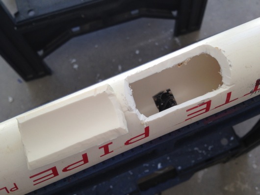
At first, I wasn't going to get all electronicky on this thing, but it just didn't seem right to have a TECHNO HAMMER without random blinking LEDs on recycled circuit boards, so, this thing needed a circuit to make random LEDs blink. It also needed a way for Mike to turn on and off the LEDs at will. I did this by embedding a standard pushbutton in the handle:
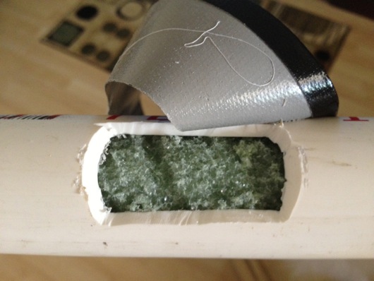
I cut a hole for the button, then cut a BIG hole behind it to allow me access for glueing. To be sure the button would be at least somewhat difficult to push through the handle, I jammed a piece of leftover green foam into the handle and behind the button before I closed up the back of the handle:
To crappily simulate leather wrapping on the handle, you can see in the image above that I took strips of Gorilla® tape and folded one edge, then wrapped up the handle at an angle. It kinda did the trick. Ya do what ya can in the time ya have, ya know?
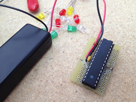
The button was in between the batteries and the LED blinking circuit. A simple momentary power-on functionality. The circuit was an Atmel® ATmega328 AVR® microcontroller (same one used in certain models of the Arduino). It was programmed to strobe the LEDs (rifle through each of them and turn them on or off many times per second, like a TV scanline). To keep the current draw to a minimum (to prevent the AVR from cooking), I had all of the LEDs cathodes return to ground through a dinky little constant current devices (CCD) from ON Semiconductor (part number NSI45020T1G). There are 12 LEDs. 12 pins on the AVR are randomly set to be on during their time slice or off. The little CCD kept the current to 20 mA for each LED. This allowed me to use red, green, yellow, and orange LEDs, regardless of their required forward voltage, since the current was always 20 mA, which they all liked. The other reason for doing it this way instead of a resistor was power consumption: The CCD is way more efficient that a resistor that dissipates heat to get the current to where it should be. The circuit was powered by two little AAA cells, so the voltage was about 3 volts DC. Since the microcontroller drew very little power and the LEDs were only on one-at-a-time, the batteries should last for days and days if left on continuously. I did run a test and they stayed lit for about 4 days before I had to assemble the HAMMER circuit. Here's the circuit and batteries:
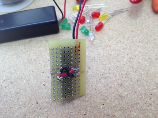
And here is the ugly underbelly of the circuit (again, time was not on my side, therefore beauty was not on the HAMMER's side):
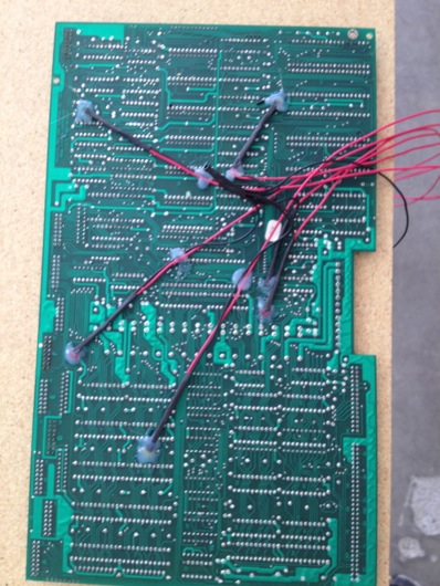
The next part of the LED circuit is the 12 LEDs that poked through the recycled circuit boards (I'll get to the boards shortly). I drilled holes in old boards pulled from an old (and quite large) oscilloscope that was given to me but that did not function. Each LED was given its own wires and a nice heat-shrink tubing treatment:
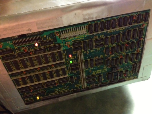
Two fairly similar old circuit boards were used for the two sides of the HAMMER. I drilled appropriately sized holes in kinda-random places and poked the LEDs through and grouped the wires together, connecting the grounds together:
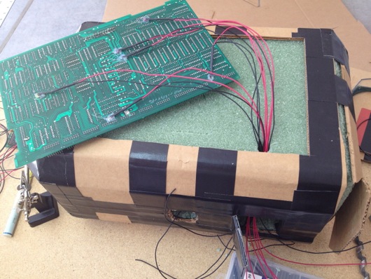
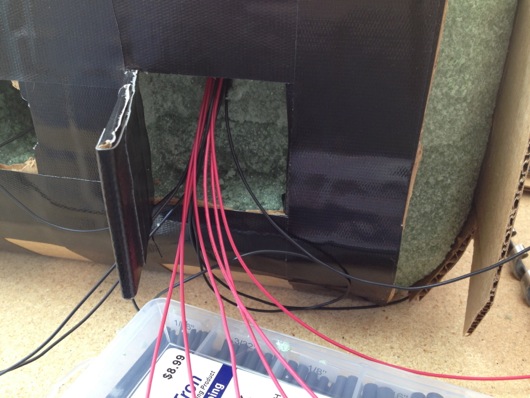
Each side's wire bundle would go through little holes in the foam core of the HAMMER and into a secret compartment that held the circuit main board and the batteries:
The compartment was crudely cut (like most of this sad but fun project) into the foam core:
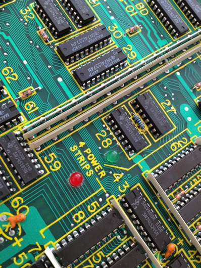
The LEDs looked right at home in the old PCBs:
The shell of the HAMMER was just cardboard faces stuck together hideously and hurriedly with Gorilla® tape. The cardboard was coerced into shape around the foam core:
The entire thing was eventually covered in Gorilla® tape:
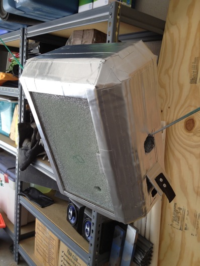
Next came the primer and silver metallicish paint for the shell. Turns out, Gorilla® tape doesn't take primer as well as I had hoped. But, it was good enough for the intended limited use:
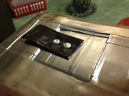
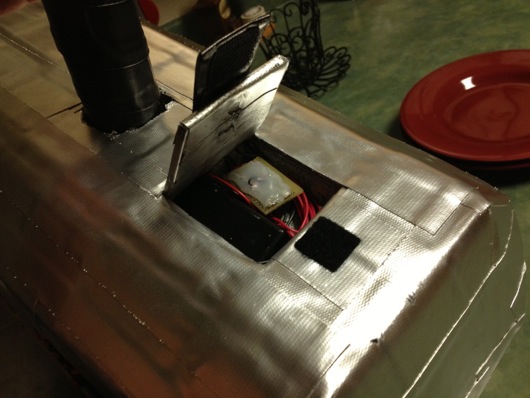
In the image above, you can see the circuit/battery compartment door and the makeshifty little riveted Velcro® closer... Thing:
Yes, it's cheesy and not at all indicative of a quality or sturdy product, but, again it serves its purpose well enough. Here's what all the crap looked like crammed into the compartment:
Finally, I soldered all 14 of the LED leads to the circuit board and connected the batteries and pushbutton and it was ready to go!
The photo doesn't show it randomly lighting LEDs, of course, so here's a video of the LEDs in action:
And finally, here is Mike actually being an Interactive Superhero with his Techno HAMMER:
Electronics and Hack Workbench
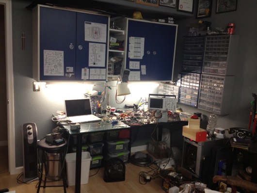
I've had a number of requests from readers to see my workbench in its entirety, as most photos of it are just backgrounds to projects. So, I thought I'd post some photos and explanations in an article. Maybe someone will get some helpful hints or perhaps someone will lend me some helpful advice. First off, here are some wide shots of the mess:
I made the table. The top is made out of three 10"-ish wide pine boards glued together side to side using biscuits. I had a custom piece of 3/16" glass to fit the top. Half of the top of the table is covered with conductive foam to keep static at bay. I ordered a couple big pieces of that from somewhere on-line, can't remember where. It's super convenient for stabbing parts into to hold them neatly. It's also great for discharging static. The legs I've had a while. They were part of a giant desk I built years ago. I got them on-line many moons ago. They have bases that are screwed to the bottom of the tabletop. They then screw into the bases. They're made of steel or aluminum or something strong like that. Under the tabletop, I put a big "X" of 3" wide interlocked pine planks for rigidity. I can stand right on the center of that table and it barely flexes.
Down below the desktop is a six-cubbyhole shelf on little rubber footies leftover from my table saw stand (that is now attached to a rolling platform I made). In each of those cubbies, I put plastic lock-top containers full of various larger items, like wall warts, scavenged PCBs from VCS and such, and cords. This is a great use of space that would otherwise be cluttered up with piles of things.
The blue cabinets came with the house. As with most of the light fixtures and some other miscellaneous pieces left behind by the previous owners, I'm guessing they're from Ikea. They're really handy. I added the little white shelves between the two cabinets. I have a benchtop digital power supply on the lowest shelf for easy access, but that's not my main power source. I'll get to that shortly.
I taped up a bunch of my most-referenced cheatsheets for things like pinouts on ATmega328's, ATtiny13's, common capacitor markings, resistor bands, ISP cables, etc. I also keep my DMM hanging right there and made a little wire hook for the leads.
The parts drawer cabinets on the right of the bench are typical types from Home Depot or Lowes. The more the merrier, as you can see. I keep groups of similar things close together. Eventually, there will be more of these. However, I have to get more creative with my space. To the right of the cabinets is a big painting that I commissioned for my Man Cave™ that I'd prefer not to move.
In some of the larger drawers, I use the conductive foam to hold my many ICs in layers to save space and for organization. I label each group with my handy Brother P-Touch labeler, like so:
Here's another angle on how I stack the ICs in the larger drawers:
I then put an index label on the front of the drawers so I can easily find families of ICs. I haven't yet found a really cool method for storing the 8 zillion resistors I have, but I do sort them by sub-1,000Ω, 1KΩm and 1MΩ drawers. Miscellaneous electrolytic caps are in one big drawer, common caps that are still in their tape from the manufacturer are generally sorted into smaller drawers.
I label the fronts of the drawers sometimes, especially when the drawer is clearly something that will always contain what it currently contains. In the case of my stacks of DIPs and whatnot, they very well organized.
I have so many parts, now, that I have built a spreadsheet to track them. A majority of the parts I have I've thrown on the end of orders because the parts looked cool or handy. When a grab bag of common transistors will only add a couple of dollars to an order, why not? AVRs are my favorite microcontroller, so I have a drawer dedicated to various renditions of that family of chip, as you can see on the middle left drawer above.
I don't know if people notice this in the background or in screenshots, but I use a 15" MacBook Pro for my benchtop computer. The battery failed, so it's always plugged into AC, now. It's now a flip-open desktop workstation, pretty much. I use this MacBook Pro to program microcontrollers and to have convenient access to the web and what not.
Our house is all Mac all the time. I have a Dell box used as a network storage server, but that's it. My regular desktop is a big-arse 27" 3.4 GHz iMac with a second 27" Cinema Display. Both are on wall-mount arms which are supposed to make my desk cleaner. However, as you can see in the photo below, all that's done is make more room for me to pile parts.
Of course, what desk area would be complete with a jackalope and an oil painting of a monkey in a fez?
About my primary power supply... I took apart a my wife's old computer that she had when we met. It was a sad, sad old computer I'd given her to get her by that I think I salvaged from my uncle's office. The power supply makes for a fantastic DC power supply. It provides very clean and reliable 3.3VDC/14A, 5VDC/22A, and 12VDC/10A power. This was crucial when I was working with peltier devices, which drew more amperage at their ideal voltages than the digital power supply could give them. This Dell power supply doesn't even break a sweat when a peltier device asks for 3.5A. The max on my digital PS is only a little shy of 3A.
I turn the supply on or off using this little toggle switch I rigged into the main jumper for the power supply.When I become ambitious about really finishing organizing my bench, I will snip all the extra wires and connectors and clean up the power supply. I'm also going to extend the voltage and ground leads and put nice ends on them to make it easier to connect and disconnect them from my many breadboards. Speaking of...
I whipped together this little adapter so that I could quickly connect and disconnect the various voltage leads from the power supply to my breadboards. I quickly got tired of screwing and unscrewing the thumbscrews on the breadboards when I wanted to switch them out. Eventually, these connectors will be on-the-ready toward the back of the benchtop and the switch for the power supply will be mounted more conveniently. The power supply will be relocated up and out of the way. Right now, sadly, it sits on two pieces of wood on the ESD foam.
When I work with my favorite microcontrollers, the AVR series from Atmel, I don't usually use a proper Arduino board, even though I tend to use the Arduino IDE. Instead, I whip together a quick circuit with either a 16 MHz or 20 MHz quartz crystal on a breadboard. I usually have three or so of these setup and ready to tinker with. I do actually have a few different types of Arduinos I've purchased with gift cards, recently. Here's an example of a typical setup for me:
I followed the recommendations from the ATmega328 datasheet for what components to put around it. There's a 10µH inductor on the analog voltage reference pin (in the photo above, it's on the Vcc pin, so ignore that). There's a 20 MHz quartz crystal on the XTAL1 and XTAL2 pins. Each of those pins is also connected to ground with 20 pF capacitors. Often times, I put a 7805 5V linear regulator on the + rails of ones side of the board and the other has either a 7812 12V regulator or LM10863V3 3.3V regulator on it. Of course, the proper capacitors near the regulators to clean up power are usually on there, as well. Don't forget the polarity diode so that you don't accidentally hook up the power supply leads backwards and cook something or popcorn an electrolytic capacitor.
As you can see from some of the above pictures and the one below, the edge closer to where I work on the glass surface gets cluttered with the parts I reuse the most.
About once every few months, I will clean up the area and put things back where they belong.
I keep my notes and diagrams and doodles in these awesome little Field Notes® brand notebooks with graph paper inside. They're about $10 for a 3-pack and each notebook has 48 pages in it. They're the perfect size to sit on the bench next to a project. Not so big that they require a lot of open space. Not so small that they're just not useful.
Last, but not least, I present my bourbon cabinet, complete with my hand-dipped (by me at the distillery) Maker's Mark® bottles. I have in my collection about 20 different bourbons. My goto at when we're out and about, of course, is Maker's Mark®. :)
That's it for the tour. If any of you have suggestions or comments, please, please leave them below in the comments section. I'd especially love to hear how you guys are storing your resistors. The ultimate trick still eludes me. I don't want to waste a little drawer for a single value, of course. Dividing up the drawers makes it too time-consuming to get one. I'm thinking along the lines of a Rol-O-Dex of resistors or something. I dunno. Comment away.
RoboStocking - AVR, Servo, Motor, IR Sensor, and BOOM!!! Merry Christmas!
At the office, we decided we were going to have a stocking decorating contest for Christmas. The rules were pretty lax, so I immediately thought of interactivity and electronics and blinky lights and whatnot. Well, that, and there was no way in you-know-what that I was going to hot glue glitter and spongy letters to a stocking with electricity being involved. Here is a video of the final product to pique your interest:
How did I do it? Easy. Some AVR programming (through my usual Arduino hackery) and some simple electronics and BOOYAH! Motion activated stocking with a Santa sign and some jingle bells.
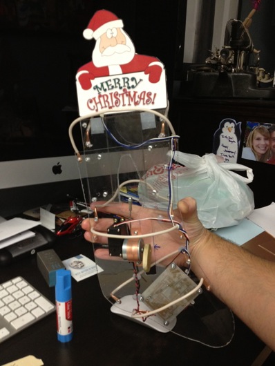
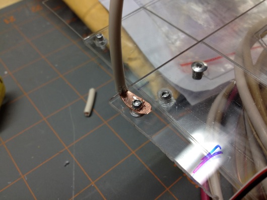
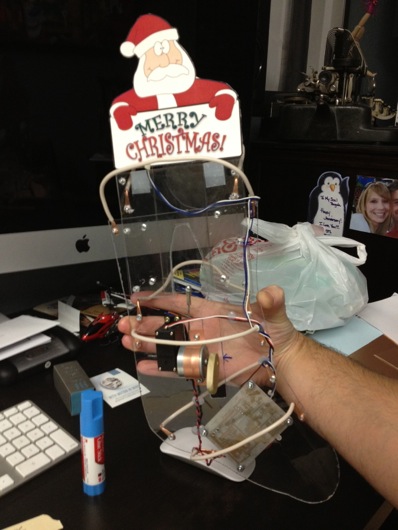
First step was to make a framework to hold the mechanics and the electronics. I used plexiglass and Lexan to support the pop-up Santa sign and to act as the general body of the mechanical works inside the stocking. The layers of plastic were riveted together.
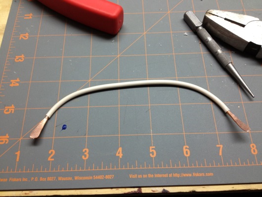
To push out the stocking into shape to make room for the guts, I took extra heavy gauge copper wire I had in my electrical drawer and used pieces of that for "ribs."
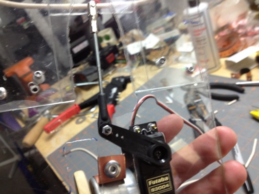
The sign was pushed up out of the stocking with a regular hobby servo and some armature work. The plastic worked as a track to keep in straight and sliding smoothly. The armature was made from parts used in RC airplanes I got at a hobby store.
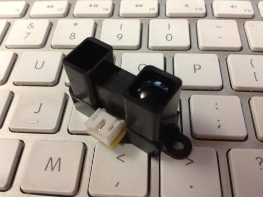
The next thing was to make it motion sensitive. That was initially going to be controller by a PIR sensor, but it turned out to be too whacky. I settled on a nice little sensor by Sharp that I picked up at Sparkfun.com. They simply alter a voltage depending upon what's in front of the sensor and how far away it is. Really simple to experiment with and get a good idea of what numbers to expect from the ADC to trigger the action.
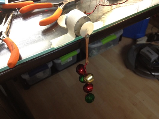
I tried a number of methods for jingling bells. The first was funny, but a bit difficult to implement on the sticking itself. It involved a wheel (or plastic gear, in this case) and a rod with the bells hanging off of it. The idea was that the motor would push and pull the bells rapidly and make them jingle. It worked on the bench, but not in the stocking.
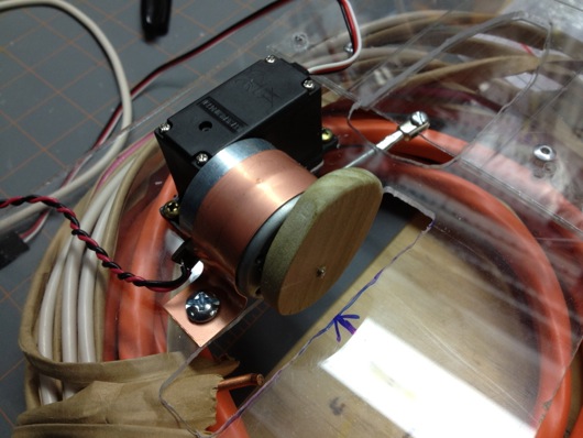
The ultimate solution I stuck with was simply a cam on a motor behind the bells. When it ran, it smacked the back of the front face of the stocking where the bells were hanging. It was essentially a big honking 12V phone vibration motor.
- Wood cam that vibrates jingle bells
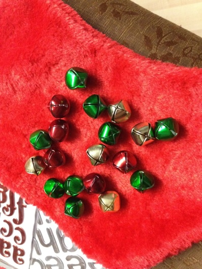
Next step: Jingle bells. I tied them to the cheap Chinese-made stocking with thin copper wire as a sort of twisty-tie thing. Worked great. I wasn't very organized about where I put bells, just wanted to get a bunch in the general vicinity of the bell thwacker motor.
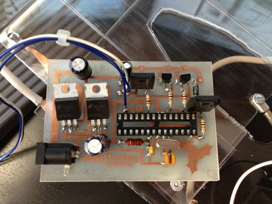
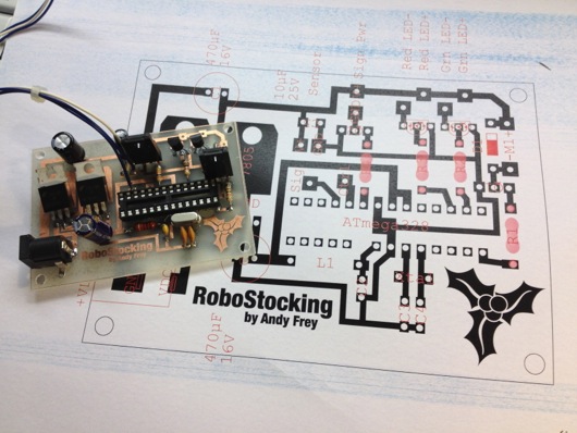
The brains behind all of this is, as usual, an AVR microcontroller. I use my own version of the Arduino IDE to upload firmware to my AVRs on the breadboard. The code is super simple. It basically just waits in a loop for the ADC to show a value from the IR sensor that meets whatever threshold I figgered out in my experiments with the sensor and ideal distances for triggering the sticking. When it gets a hit, it turns on the MOSFETs for the servo (the sign) and the motor (the bells). It start the motor spinning for hitting the bells and pushes up the sign. After a few alternating blinks of the [not-added-at-this-time] LEDs, it retracts the sign and stops the motor and cuts power to them both. That's pretty much it. Here's the RoboStocking motherboard:
I even put holly on the board in the etch. :) Because the wall wart that powers this thing outputs about 20VDC, I put a LM7805 5-volt regulator on the board for the logic stuff and another LM7805 regulator for the motor and servo. There was no reason to run the motor at its full 12 volts. It was only smacking the back of the stocking. There are two regulators because the power draw of the circuitry plus the motor plus the servo was causing the AVR to shutdown. Running on their own circuits gives them each the full power available through the individual regulators.
As always, I drew the circuit board in Adobe Illustrator, flipped it and printed it on my Samsung black and white laser. I've found that running the transfer paper through the laminator four times makes the toner really adhere to the copper without problems. I've notice that after four times, when you drop the board with the transfer paper stuck to it into the water bath, it dissolves off the board pretty quickly. The etch afterward is much higher precision, as well.
The only thing left was to draw a cute sign for the slide-up. It took me a bit of trial and error, but I finally drew a decent cartoon Santa in my normal style and slapped a Christmassy looking font in the sign part of the slide-up thing. This setup makes it look like Santa is just hanging out in the top of the stocking. When he slides up, the actual sign is revealed below him, as if he's pulling it up for you.
With everything assembled, the guts of RoboStocking look pretty cool:
What makes this story funny is that I was not able to finish this silly thing in time for our company Christmas party. I had to put the final touches on it over the weekend and bring it in the Monday following the party. It was met with great reviews, but could not win the contest that had past. :( Oh, well. There's always next Christmas. Sound and lights will be added, I assure you. ;)


