upgrade

DODOcase for iPad 2 DIY Magnet Upgrade

I LOVE my iPad 2. To protect it, I HIGHLY recommend the DODOcase (http://www.dodocase.com/products/dodocase-for-ipad2). My only complaint would be the lack of a magnet in the case to activate/deactivate the iPad through its little magnetic sensor, which is used by other cases, like the foldy-flippy one from Apple (http://www.apple.com/ipad/smart-cover/). What to do? Hack, of course! But, first, I emailed the DODOcase peeps and suggested the feature to them and even sent them links to my source of delicious rare earth magnets, K & J Magnetics (http://www.kjmagnetics.com/). There are thin little rectangular magnets that can easily be embedded into the cardboard cover underneath the backing.

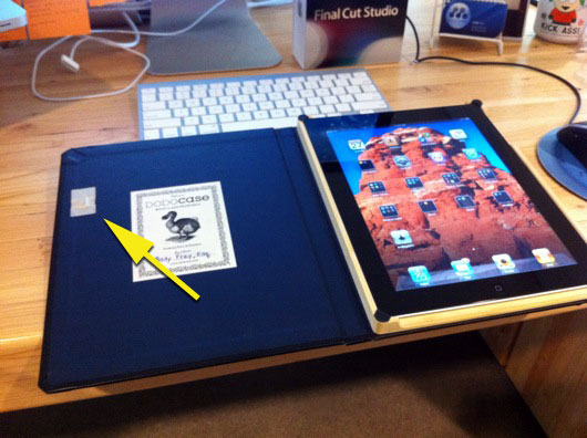
For now, my magnet sits on top of the inside cover:

Magnet added to DODOcase

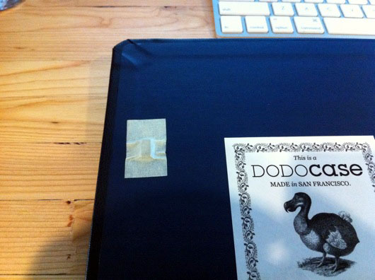
Here is a close-up:

Close-up of magnet on DODOcase for iPad 2

When I have a spare couple of minutes, I'll whip out the X-acto knife and make a neat little compartment for it under the blue liner of the cover.

Hope this helps you other DODOcasers out there!

Hack the SparkFun Big Red Dome Button!

Needs more shine! The light bulb inside is medium OK in its ability to attract insects and people with ADD, but I wanted a little better (not too much, though). I also wanted signage. This is a super-simple project that anyone with even questionable soldering skills can pull off. Plus, there is enough room behind the red part of the button to put most any LED you like. Finished Dome Button Upgrade: Lower power, better

First, let's start with what the awesome big red dome button from SparkFun looks like as shipped:

SparkFun Big Dome Pushbutton as shipped

Eet's Oh-Kay. What's more fun than a big-honkin' red button?? It could wind up as a History Eraser button like on the 90's cartoon Ren & Stimpy. Maybe a self-destruct button? I'm going to make something similar to the button from the movie The Box. Nice wooden case, flip-open lid, big lettering that reads, "DO NOT PRESS" and pulsing backlighting. How can you NOT press a button like that? When the button is pressed, it will play Daffy Duck going nuts.

Here is the original light bulb lit by 12 volts AC:

Original light bulb for dome pushbutton

It's OK and looked decent behind the red dome, but it draws a bit of power and it's old fashioned and not as neato as LEDs.

We start by flipping over the button and checking out what we have to work with.

Under the dome button

We need to take this thing apart to the point that we have all the pieces sitting on the desk, ready to be upgraded. The switch and light assembly twists to unlock and then pulls out of the center of the button.

Switch and light assembly

Next, pull out the lightbulb from the assembly. It simply pulls out. Just tug on it, maybe wiggle it a bit, and it will come out eventually.

Light bulb removed from switch assembly

Unscrew the big white plastic nut from the back of the button to release the main part of the dome button from the bigger black base thing. You'll be left with the basic parts and you can display them neatly like I did:

Fully disassembled big dome button

To release the top red part of the button, the dome, from the whole thing, you need to squeeze the little white tabs inside the center of the button where the switch and light assembly was.

White tabs in center of button hold top in place

Once that red dome part of the button is loose from the black base, you can pry the red off the white with a little screwdriver or other similar implement in order to get to the pulp and juice of the fruit. What?

Prying open the red dome

Now we have access to the disc inside the red dome to which we can affix signage.

Inner sanctum of dome button

I took a quick measurement of the white disc and fired up Adobe Illustrator (which I also use to create my circuit board designs) to make the appropriate sticker. I printed the words on full-sheet sticky-backed laser printer paper, available at many places. If you can't find it, this project is probably over your head.

Warning label for dome button

For this hack... I mean, upgrade, we're using my favorite little SMD LEDs from SuperBrightLEDs.com, or pick your favorite supply source. They have three little white LEDs in a single, easy-to-solder surface-mount package. I've used these many times for projects like the Iron Man arc reactor, the LED reading lamp, and a new project about to be posted (you'll have to check back to see it).

5mm triple white LED SMD package

Two things happened in this next step and I forgot to photograph the process, but I took a strip of IDE cable and peeled a section of three wires from it. I then placed that three-conductor cable and placed it inside the perimeter of the white part of the button where the light bulb used to shine through. I marked it to the length of the inner circumference of the white thing. I then divided that by 3 and chopped it in the two spot and trimmed back the insulation on each of the ends of the cables. I then soldered each of the three LEDs in each of the three SMD LED packages in series. Basically, I just daisy-chained the LED packages together. At one end, I soldered a single, 22 gauge wire to the cathodes of the LED package. On the other end, I soldered another 22 gauge wire to the anodes of the LED package. Look at the second photo of the interior of the dome below.

I lined the inside of the dome with sticky-backed foil, which I picked up from Home Depot. It's in the plumbing and heating section and they use it to seal and for reflective insulation, I think. All I know and care about is that it makes a great reflective surface for scattering light. I used it in the Man Cave lighting upgrade  and 12 VAC power supply project.

Dome button lined with sticky foil

Here is a closer shot of the LEDs and the IDE cable:

Notice the LEDs cabled together

The foil tape holds everything in place. The positive and negative leads then are routed out through the hole in the center where the light bulb used to be located.

As always, I marked the leads for positive and negative.

Leads marked with black/red

And here is the main part of the button put back together:

Reassembled dome part of button

Now, put the dome assembly back into the black holder and put the spring back:

More put back togetherness

Next, we need to prepare the switch thing a bit. The brass clips inside the switch holder need to be removed. We don't need them at all. You could solder the leads from the LEDs to the brass thingy, but I didn't. Use a small screwdriver again to pry the side away from the switch. There is a notch that the plastic snaps into on the switch. Once you pry that away, the plastic holder will slide off the switch easily.

Pry off plastic switch/bulb holder

Next, remove the brass clips. They will be bent pretty well in the process. Doesn't matter. We don't need them.

Brass bulb clips removed

Route the leads through the plastic switch holder and twist it back into the button.

Route leads and reinsert holder

Next, route the leads out the sides of the holder so that the switch will snap back into place.

Leads out the sides, switch back in place

Connect the leads to your 12-volt DC power supply with a limiting resistor (depends on your LED specs) and it should light right up!

Viola! Lighted and customized big red dome pushbutton!

USB Foam Dart Launcher Assimilated (Partially)

A coworker walked up to my desk and handed me this USB-controlled Nerf-esque dart launcher thing from Think Geek because it wasn't working. If it was dead, I thought I'd at least get a number of little motors and gears and whatnot. I took it home, removed all the screws and completely dismantled it to see how it works. It's ingenious inside. I won't get into it, but it's pretty cool. I decided to put it back together, sans its main circuit board. Everything appeared to work, as far as I could tell. I figured out that the darts were gripping the nozzles on the barrel of the gun to tightly, so I jammed a needle nose pliers in the back of the dart and spread 'em open a little more. That fixed it.

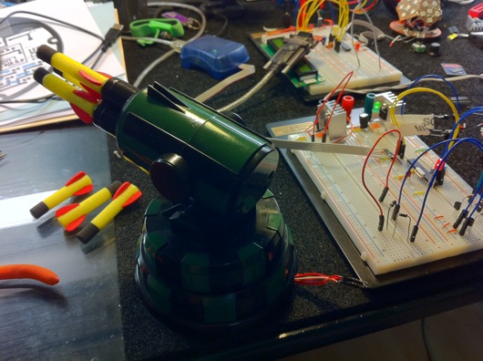
Next question: What to do with this thing. I removed the main board and had all the wires for the motors and the switches hanging out the hole where the USB cable used to be. Man Cave Security called and said we needed some kinda defensive system to connect to the new [fake] talking alarm pad. I'll post the rest of the photos of the finished weapon when it's completed. In the meantime, here is the reassembled launcher with a new 12-pin header soldered to the wires for easy breadboarding:

Hacked USB Dart Launcher

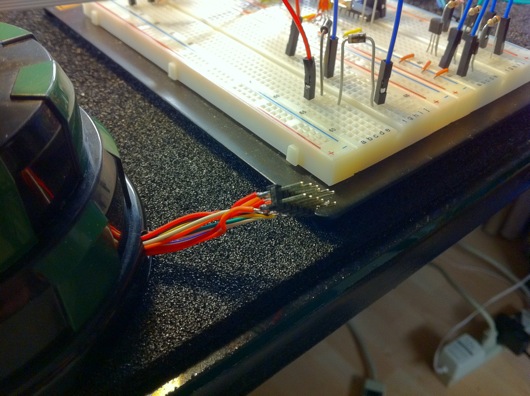
Here is a close-up of the header hanging out the back of this thing:

Launcher 12-pin Header

So, like I said, once I get some more work completed on this bad boy, I'll post the fun photos.

Turn a Servo Into an Inexpensive Geared Motor

In my UME Mark II's (UME = "Useless Machine Ever"), originally I would program an Atmel AVR microcontroller to turn an RC servo forward and backward using timed pulses like you're supposed to. But, when you want to build many machines, microcontrollers are not the way to go. Simple polarity-changing circuits are the way to go. But, you still want the RPMs of a servo without the hassle of the pulsing control. So, you hack the servo and make it a geared motor. Easy! Here's how... Futaba S3004 servo intact

Grab yourself one o' them thar RC servos for a good price at your local hobby shop or on-line. They look so innocent. If you listen, they make a whimpering sound because they know that phillips head screwdriver in your hand is there for kicks.

Take off the armature thing.

I hope that my lack of knowledge in all that I do is entertaining and not a hinderance in the usefulness of these posts. :) So, that said, look at the above picture. I took off the star-shaped armature thingie.

Remove l-o-n-g screws holding the whole thing together.

Unscrew the screws in the bottom of the case of the servo-soon-to-be-geared-motor.

Take off the back. See neato circuitry.

Remove the cover on the bottom of the servo. You'll see nifty circuitry and the spots where the three wires are soldered to the board.

See the wonderful gears and pins and such

Carefully remove the top of the servo that contains the gears and pins and lubricating goo. I bold the word, "carefully" because you need to put this all back in the way it came out. If you can't get it all back together, you will have a nice pile of gears, pins, circuitry, a plastic case, some wire, and a neato DC motor. Take pictures if these don't cut mustard. They can help back track the destruction and make it reversible.

Shimmy the neato circuitry and motor guts out of the plastic case.

Shimmy the neato circuitry and motor guts out of the plastic case. The potentiometer (black thing standing on thick leads opposite the motor) is used by the circuitry to indicate where the shaft is positioned at any given moment. Once the hack is complete, it will be unused. I'll give you some options for it later on.

Desolder the three wires from the board.

I used my ACMG robot (aligator clip magnifying glass) to hold the guts while I worked. Desolder the three wires from the board. Remember not to heat the stuff you work on with the soldering iron for too long. That heat can travel to components that don't like warm weather and can cause severe rash or sunburn or death.

Solder the red and black wires to the motor leads.

Solder the red and black wires to the motor leads. Once you do this, the servo is simply an inexpensive geared motor. The robot makes this very easy to do. You can use a wife, girlfriend, son, daughter, or even an uncle to hold the work, but they're nowhere near as steady as a the alligator clips.

Route them between the pokey little component leads.

Wires soldered. Route them between the pokey little component leads sticking out of the bottom of the neato circuit board because there isn't much room between the PCB and the case cover and the wires have to travel across the board to the hole in the case. I like the path I chose. It looks like a... Well, it doesn't look like anything, but you can pretend.

Looking at the underside of the top of the servo

View of the servo... Er, almost-a-geared-motor (now) looking at the underside of the top of the servo (with the gears) and the top of the main body (at right). The bearings on the black gear are tiny and cool. That black gear has a little nub on it that acts as a stop at one of two positions 180 degrees from each other in the rotation of that shaft. We need that snipped off and trimmed.

See the nub? It's what I'm holding onto with the wire cutters.

See the nub? It's what I'm holding onto with the wire cutters. You need to trim that down flush with the shaft and with the face of the gear (the part of the gear parallel to the back side of the wire cutters in this photo). That will prevent the gear from stopping against the stops that are built into the case of the servo.

Make sure there are not bits left behind or you will hear clicking as those remnants click past the stops in the gear box.

Look on the right side of the gear, just below the bearings on the rear of the face of the gear. Make sure there are not bits left behind or you will hear clicking as those remnants click past the stops in the gear box. I suppose you could clip the stops, as well. But, you can see in this photo that I have a little bit of trimming to do, yet.

Use your new geared motor at will.

Use your new geared motor as you wish. I learned to circumvent the circuitry on these from various posts on the IntarWebs. It's not hard at all. If you screw up, the servos I found locally at the hobby shop were only about $12, so it isn't the end of the world if you fubar one. In the photo above, you can see the unfinished tops and "robotic arms" from one of the Useless Machines (see post on my site about this device).

Cigar Coolidor (Wine Cooler + Humidor = Coolidor)

This is one of the first "major" projects I built that involved electricity and electronics. This project makes it super-simple for me to manage my expensive (for me) cigar collection with minimal effort. It uses a 6-bottle wine fridge, some custom-cut Spanish cedar, and a Cigar Oasis XL electronic humidor humidifier. Completed coolidor

The fridge was about $99 on-line (I may have gotten it at Wal-mart's website, I can't remember). The Cigar Oasis was about $90 on-line. The Spanish cedar was the expensive part. I think I spent about $160 for a 6' piece of uncut and unfinished wood. I had to have the people at Woodworker's Source (Phoenix area, near my home) rip the big plank down to nice and thin planks with which I could line the fridge. The cutting part was about as much as the plank of cedar.

I kinda rushed this project, as you can see. The shelves are not completely level and don't fit perfectly. Most of my time was spent measuring and shaping the pieces so that they would fit without needing glue or fasteners. It turned out well enough to do the job.

The electronics weren't too tough. It was my first project that involved busting open a device that used wall power. That was unnerving. But, it isn't rocket science. I just opened up the back of the fridge, found where the power supply fed the electronics of the fridge at ~5V and tapped the power cord of the Cigar Oasis into that line. The Cigar Oasis doesn't draw a lot of power, so it seemed the power supply wouldn't mind. Er, at least, in the two or three years it's been running in my Man Cave™, it hasn't quit or caught fire. ;)

Like I just said, it's been running for about two or three years and I've filled the Cigar Oasis maybe twice. Other than that, I haven't touched the humidor for maintenance, only to select cigars to enjoy. The fridge keeps the temperature at 70 degrees fahrenheit and the Cigar Oasis keeps the humidity inside the fridge at about 70%.

Coolidor after 2 or 3 years

The photo above is the coolidor after about two or three years. I've loaded and unloaded lots o' cigars. The little readouts on the Cigar Oasis and the little electronic hygrometer don't ever match. The cigars smoke perfectly, so the "63%" showing on the gadget there is low because, when you open a humidor in Arizona, the humidity escapes rapidly... Because we're in a desert. But, when it reads about 65% upwards to %68, the cigars are happiest in my experience. To get the optimum humidity, I have to keep the Oasis set at about 68%.

This project is easy to do. If you're a cigar geek, I highly recommend taking a little time to build a humidor that can manage itself. Set and forget. It's awesome.