AC Current Detection with Allegro AC756 Linear Current Sensors

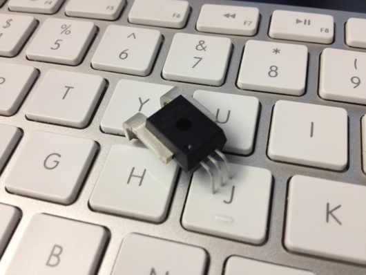
I received an Allegro AC756KCA-050B from my friends over at Element14 (Newark.com) and I wanted to see if this little gadget would make it easy to sense when the doorbell was ringing. As it turns out, it's completely overkill for the task, so I won't use it for my remote brass marine bell door chime thing (mentioned in previous articles). BUT, I did want to experiment with it to see what I could get from it. This is the true story of how I got something useful out of it and how I manage to have fun playing with electronics while being a complete hobbyist. First of all, here is a picture of one:

Picture of Allegro ACS756KCA-050B AC Current Sensor

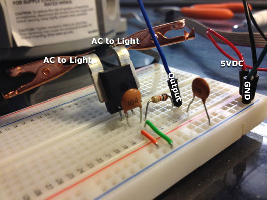
It totally looks like a micro robot that pierces the fingertips of cheating poker players. You don't see that? OK, maybe the the first things you notice are those big-ass leads at the back. Why so big? Because the datasheet says this bugger can handle up to +/- 50 A of current. Wow. The next thing I noticed was the dot in the corner of the face of the chip. I blame A.D.D. I'm guessing that most people would notice the three little leads (or fingertip piercers). Those leads (from left to right, 1 to 3) are Vcc, GND, and Viout. The output side (non-AC side) runs on 5VDC. With a couple of capacitors and a resistor, it's ready to go. Here's what my little test rig looked like (I labeled it because I am proficient with Photoshop) (no, for realz: I'm pretty good with Photoshop and I can do more than labels with drop shadows):

AC756KCA on Breadboard

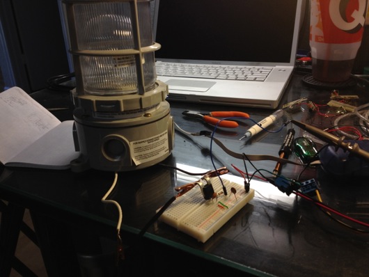
When our office expanded AGAIN, we bought a new space that had some cool "jelly jar" light fixtures that were left behind (my electrical supply sales friend told me that was what they're called in the industry). I got a couple of them for fun. I might put a red LED light inside one and mount it above the Man Cave™ door to warn my wife of experiments in progress. Here is the lightbulb connected to the ACS756:

Lightbulb Connected to ACS756 Current Sensor

The first thing I did was hook the output of the ACS756 to one of my AVR microcontrollers. When I read the values via an analog (ADC) input on the AVR, I printed the values every second to the terminal and saw values generally around 510 (on a scale from 0 to 1023). At first, before I turned on my brain, I couldn't figure out why I was only getting that one silly value (or close to it), regardless of the state of the power switch on the lightbulb. What I failed to realize was that the signal coming from the device was an AC wave, of course. I needed to sample a bunch quickly and then plot that out to see the wave.

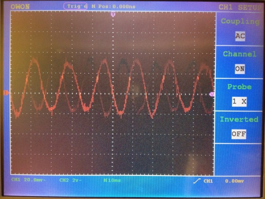
Next, I connected the output to my oscilloscope. I was able to see a waveform when I powered on the lightbulb. It was a bit more faint than I thought it would be, probably because I hadn't read all the way through the datasheet at this point. I guess an op amp would take care of that if I wanted the wave a bit bigger. I set the scope to see if the frequency was 60 Hz and it looks like it was (60 Hz, 16.7 ms each cycle). So, I assumed that was a good read from the AC current side of the chip. Here's the scope screen with the lightbulb turned on:

Scope: Lightbulb ON

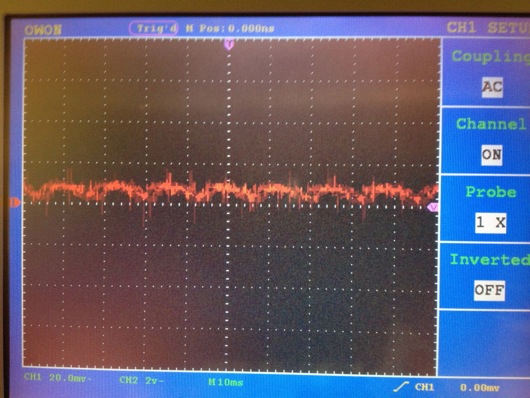
With the lightbulb turned off, the waveform looked like this:

Waveform of lightbulb while OFF

When I turned off the light, the wave went to nearly gone, but, as you can see, some kinda transient something or another caused a tiny little flutter in the scope display when the light was off, which I suppose could be controlled if I read the datasheet more intently. When I turned on the lightbulb, the wave was definitely there and there was most definitely a difference.

Now, as I said in the beginning of this article, my original intent for this device was to sense when the doorbell line was energized and ringing the chimes in the house so as to trigger a Zigbee wireless call to a remote device on our back patio which would then fire a solenoid at a brass marine bell. I think I've said it before in a previous article: Yes, this is total overkill and I could easily run to Home Depot or Lowe's and get a remote doorbell to hack and have it running in a couple of hours. But, where's the fun in that??

RoboStocking - AVR, Servo, Motor, IR Sensor, and BOOM!!! Merry Christmas!

At the office, we decided we were going to have a stocking decorating contest for Christmas. The rules were pretty lax, so I immediately thought of interactivity and electronics and blinky lights and whatnot. Well, that, and there was no way in you-know-what that I was going to hot glue glitter and spongy letters to a stocking with electricity being involved. Here is a video of the final product to pique your interest:

How did I do it? Easy. Some AVR programming (through my usual Arduino hackery) and some simple electronics and BOOYAH! Motion activated stocking with a Santa sign and some jingle bells.

First step was to make a framework to hold the mechanics and the electronics. I used plexiglass and Lexan to support the pop-up Santa sign and to act as the general body of the mechanical works inside the stocking. The layers of plastic were riveted together.

RoboStocking plastic frame and copper ribs

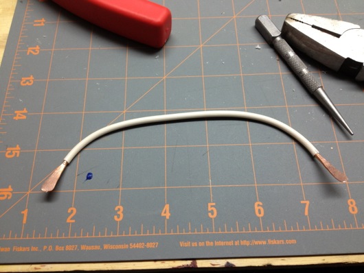
To push out the stocking into shape to make room for the guts, I took extra heavy gauge copper wire I had in my electrical drawer and used pieces of that for "ribs."

Heavy gauge copper wire as ribs

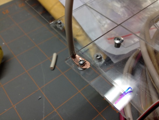
Copper rib bent 90º and riveted to main plastic frame

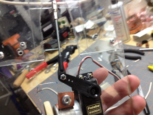
The sign was pushed up out of the stocking with a regular hobby servo and some armature work. The plastic worked as a track to keep in straight and sliding smoothly. The armature was made from parts used in RC airplanes I got at a hobby store.

Servo Santa sign linkage

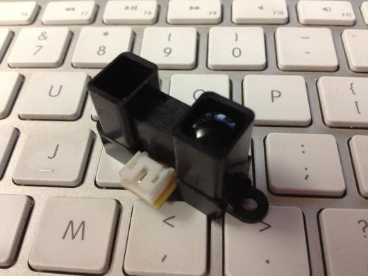
The next thing was to make it motion sensitive. That was initially going to be controller by a PIR sensor, but it turned out to be too whacky. I settled on a nice little sensor by Sharp that I picked up at Sparkfun.com. They simply alter a voltage depending upon what's in front of the sensor and how far away it is. Really simple to experiment with and get a good idea of what numbers to expect from the ADC to trigger the action.

Sharp Long Range IR Proximity Sensor (2Y0A02)

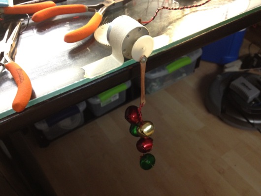
I tried a number of methods for jingling bells. The first was funny, but a bit difficult to implement on the sticking itself. It involved a wheel (or plastic gear, in this case) and a rod with the bells hanging off of it. The idea was that the motor would push and pull the bells rapidly and make them jingle. It worked on the bench, but not in the stocking.

First attempt at mech-jingle bells

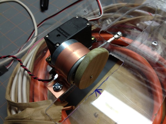
The ultimate solution I stuck with was simply a cam on a motor behind the bells. When it ran, it smacked the back of the front face of the stocking where the bells were hanging. It was essentially a big honking 12V phone vibration motor.

 Wood cam that vibrates jingle bells
Wood cam that vibrates jingle bells

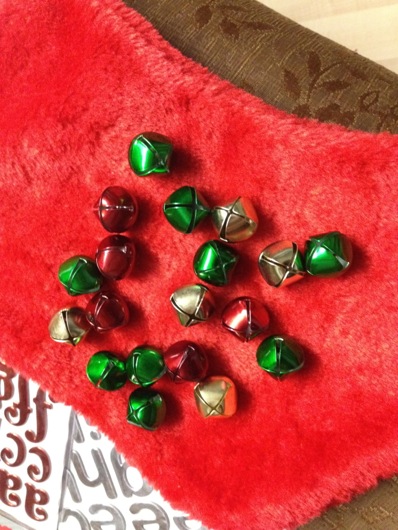
Next step: Jingle bells. I tied them to the cheap Chinese-made stocking with thin copper wire as a sort of twisty-tie thing. Worked great. I wasn't very organized about where I put bells, just wanted to get a bunch in the general vicinity of the bell thwacker motor.

Jingle bells randomly stuck to the stocking's face

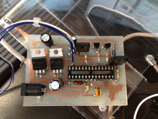
The brains behind all of this is, as usual, an AVR microcontroller. I use my own version of the Arduino IDE to upload firmware to my AVRs on the breadboard. The code is super simple. It basically just waits in a loop for the ADC to show a value from the IR sensor that meets whatever threshold I figgered out in my experiments with the sensor and ideal distances for triggering the sticking. When it gets a hit, it turns on the MOSFETs for the servo (the sign) and the motor (the bells). It start the motor spinning for hitting the bells and pushes up the sign. After a few alternating blinks of the [not-added-at-this-time] LEDs, it retracts the sign and stops the motor and cuts power to them both. That's pretty much it. Here's the RoboStocking motherboard:

RoboStocking motherboard with socket for ATmega328 microcontroller

I even put holly on the board in the etch. :) Because the wall wart that powers this thing outputs about 20VDC, I put a LM7805 5-volt regulator on the board for the logic stuff and another LM7805 regulator for the motor and servo. There was no reason to run the motor at its full 12 volts. It was only smacking the back of the stocking. There are two regulators because the power draw of the circuitry plus the motor plus the servo was causing the AVR to shutdown. Running on their own circuits gives them each the full power available through the individual regulators.

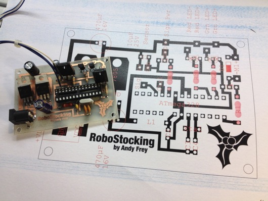
As always, I drew the circuit board in Adobe Illustrator, flipped it and printed it on my Samsung black and white laser. I've found that running the transfer paper through the laminator four times makes the toner really adhere to the copper without problems. I've notice that after four times, when you drop the board with the transfer paper stuck to it into the water bath, it dissolves off the board pretty quickly. The etch afterward is much higher precision, as well.

Board with printout of circuit to help me place components

The only thing left was to draw a cute sign for the slide-up. It took me a bit of trial and error, but I finally drew a decent cartoon Santa in my normal style and slapped a Christmassy looking font in the sign part of the slide-up thing. This setup makes it look like Santa is just hanging out in the top of the stocking. When he slides up, the actual sign is revealed below him, as if he's pulling it up for you.

Santa sign on RoboStocking

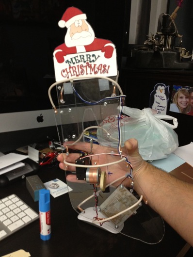
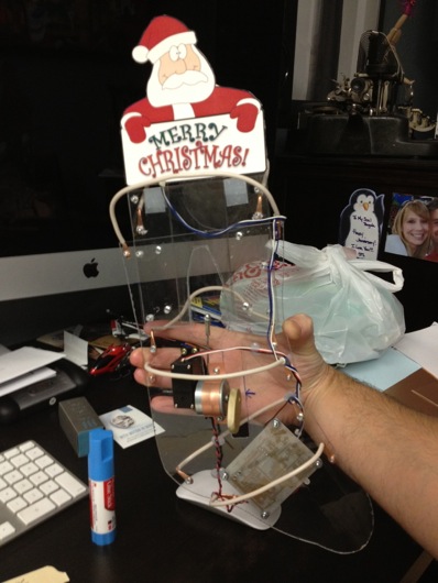
With everything assembled, the guts of RoboStocking look pretty cool:

RoboStocking with SantaSign and RoboGuts

What makes this story funny is that I was not able to finish this silly thing in time for our company Christmas party. I had to put the final touches on it over the weekend and bring it in the Monday following the party. It was met with great reviews, but could not win the contest that had past. :( Oh, well. There's always next Christmas. Sound and lights will be added, I assure you. ;)

Solenoid-Powered 6" Brass Bell

I mentioned in an earlier post that I was working on a project that would help us to hear the doorbell out on the back patio. The problem is that the doorbells themselves are upstairs inside the house and difficult to hear. No matter how many times we tell guests to just walk in and come to the back patio, they still try to ring the doorbell and we don't hear them. This is also another write-up on a product for the kind folks at Element 14 (Newark.com). What item did they send me this time around? The 12-volt solenoid (Newark SKU: 20M1816) that's going to ring my bell! This solenoid is powered by 12 volts DC. It's super-easy to hook up: Just two wires and BOOM! They're inexpensive and quite rugged. The hole through the center is large enough and the coil is long enough that I was able to stick a spring inside. I think I'll be ordering some more of these. They will come in quite handy on other interactive projects.

Newark has a product on the Ledex stuff: http://www.newark.com/ledex/

This project is going to be remotely fire a solenoid under a 6" brass bell mounted on the wall outside the back patio door. The solenoid will be triggered by a simple 5-volt pulse from an AVR microcontroller that will receive commands remotely over Xbee wireless from the doorbell (the doorbell side has yet to be worked out).

Here is a video of the solenoid and the bell triggering from a 5-volt button push:

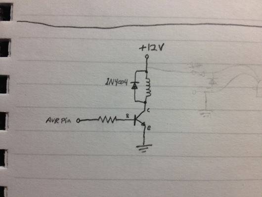
The circuit is super-simple: A TIP41A NPN transistor is used to control the 12 volts that power the solenoid. Any 5-volt input can fire the solenoid and hold in the armature. I added a spring to the inside of the solenoid that loads up when the solenoid is activated. When the 12 volts is gone, the spring shoots the armature out and the heavy end of it strikes the inside of the bell. Couldn't be simpler.

Here is the circuit sketched out:

Solenoid bell circuit sketch

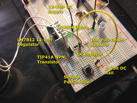
Here is the circuit on the breadboard:

Breadboard solenoid bell circuit labeled

As I figure out more of the entire project, I will continue to add to this post.

AVR Serial Communications Using XBee RF Modules

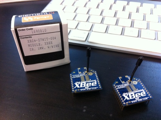
I was contacted by Element 14 (Newark.com) recently about doing some product test drives using some of the products from their line card. I took two to three seconds to think about it. I know, tough one... XBee S2 ZigBee RF modules by Digi International

I have been chomping at the bit to use ZigBee wireless technology in a project. Digi International makes some REALLY cool and easy-to-use ZigBee RF modules that bring ZigBee technology down to a level that even I can implement without more than a few terse passes at a wireless book and a couple of datasheets. So, the first piece of loot I requested from Element14 was an XBee S2 module. I would love to link you to this module at Newark.com, but it appears to be gone. That is sad. BAck to our story... There was a spending limit on my test-drive loot. I ordered one XBee S2 module on my tab. The other XBee module was sent to me courtesy of Element14.com.

The ultimate project is based on a need at our house: We hang out on the back patio quite a lot and when we invite guests over, even after we ask them to just come on in, they ring the doorbell and we can't hear it out on the back patio. The leave disappointed that we would not be home when we said we would be. I'm kidding. Usually they do walk right in.

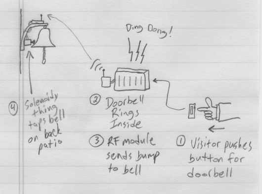
DIY remote doorbell using XBee modules

The first drawring I made used a brass marine-type bell with a string that was routed from the front door around to the back patio. Guests could simply tug on the string to get our attention. My wife wasn't keen on the network of pulleys and string required to make that happen. The drawring above is the watered down, no-fun-havin' version. Awe, who are we kidding? It's still fun. It's ALL fun! What's not to love about electricity and radio frequency waves making things do stuff??

Plan B for the remote doorbell is much cooler and much more electronic: Rig XBee to the house doorbell system so that it can signal a solenoid type of thing to plink a brass bell on the back patio. Not as Wallace & Gromit as the pulleys and string, but still pretty darn cool.

Oh, let me get this out early: Yes, übernerd, I know that XBee is overkill for a simple remote doorbell. The final version of this thing will use a simple little OOK (on-off key) RF module pair that simply sends on or off (button pushed or not). For now, though, this is a great way to get to know Señor XBee and his amigos.

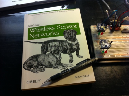
Building Wireless Sensor Networks by Robert Faludi

Before I go any deeper into this project, I want to HIGHLY recommend a book on the subject of AVR/Arduino microcontrollers and ZigBee networks. If you're interested in this stuff, go out and get a copy of Building Wireless Sensor Networks by Robert Faludi, published by O'Reilly. I also highly recommend you do NOT do what I did: Do not buy the book, read it cover-to-cover, and do absolutely nothing hands-on. I wound up having to re-read large portions of the book again to get my bearings with the XBee modules from Digi. Try to have an AVR microcontroller (or Arduino) and a couple of XBee modules on hand when you start reading the book.

Now, the first thing I have to say about these modules is that they are stupidly simple to setup and get running, as you'll see in this post. I was asked to do a write-up by Element14.com and this is an easy one: These are AWESOME. There are plenty of sources on the Web for connecting XBee modules. I won't go into major detail, but I will show you how quickly you can get to AVR microcontrollers talking wirelessly with two Digi International XBee S2 ZigBee RF modules. Keep reading...

The process for getting two XBee modules talking, or, in this case, two AVR microcontrollers talking via XBee modules, it this:

  1. Get two XBee modules (Farnell.com part 1690810) and a handful of 10-pin, 2mm headers used to adapt the non-breadboard-friendly XBee pins to your breadboard
  2. Get one or two AVR microcontollers with UART capability (and supporting components) or one or two Arduinos
  3. Build cheesy adapters for the XBee modules so that they fit your breadboards
  4. Download the X-CTU Windows program to upload newer firmware and appropriate firmware to the XBee modules (this relates to setting up one XBee module as the "coordinator" and one as the "router" [see book above])
  5. Put some serial-savvy code on an AVR chip or Arduino and connect its UART pins to one XBee module's DIN and DOUT pins
  6. Connect the other XBee module's DIN and DOUT pins to a serial cable to your computer
  7. Send commands through the air to the AVR from your favorite terminal program

OK, that's oversimplified, but if you're comfortable with building circuits and working with Arduino or AVRs, that's all there is to it. Take a look at this setup in action (and please forgive the hastily shot and edited video):

If you're a Mac person, and I know I am, you're going to disappointed in the lack of a Mac firmware updater for XBee modules. However, it is pretty darn simple to fire up Boot Camp or VMware and update the radios the way the aforementioned book suggests. I just picked up my breadboard with the two radios and the AVR and the USB-RS232 cable and plopped it on my desk next to my iMac and fired up VMware and did it. Nice and easy, save for one issue: Once the upload of the firmware was complete, Windows XP Pro went to a BSoD (Blue Screen of Death). Pretty awesome. Let me say that it is no secret that I hate Windows. I'm disappointed in Digi for note having a Mac client to update firmware on the XBee modules. Maybe someday...

If you follow the book, you can get two AVRs or a computer and an AVR communicating in pretty short order. The code I wrote for the AVR to receive the serial commands from the computer to switch the traffic LEDs was easy and it actually worked the first time. It's really cool when stuff works as advertised.

If you've got some communicating you need to do between your microcontrollers, especially multipoint stuff, XBee modules are the way to go. Soooooo easy to setup and use. Head over to Newark.com or your favorite source for Digi International products and start mesh networking your DIY gadgets.

This post was originally about the remote doorbell idea. I'll write a separate post about that completed project using simpler RF modules from SparkFun, as ZigBee is WAY overkill for a remote doorbell, unless you're putting little remote bells or buzzers all over your mansion.

Desktop Warp Core - The SMD LED Strip Years

I threw together a video of the warp core's control circuit and eight stupidly bright white SMD LED strips for the rings. The original rings were going to be through-hole bright LEDs, but I realized how much soldering and drilling would be required for that. That is dumb and painful. So, factory-built strips of LEDs, complete with self-adhesive backing, resistors, and snap-on wire ends ready for 12-volt DC power it is! Here it is in action:

There will be more to come as we start to construct the body of the warp core.

Fix Missing Comments Problem in Notepad WordPress Theme

Some of you regulars may have noticed that comments were magically not appearing at the bottom of some of the posts on this blog. I snooped around in the code behind the theme and discovered one line of PHP that caused comments to sometimes show and sometimes not show. I'd like to share what I found to help others who are having the same problem. Let me add this little tidbit: I LOVE this Notepad theme by Nick La (http://ndesign-studio.com/wp-themes). His work is Very excellent. I contacted Nick through his contact form to let him know about the one-line fix to the comments.php file in his theme. I had installed this theme when my blog was running as WordPress 2-something, not 3.

Here is the easy fix: Edit your comments.php file and find this line (roughly line 24):

wp_list_comments('type=comment&callback=mytheme_comment');

Change it to this:

wp_list_comments(array('callback'=>'mytheme_comment'));

Update the file (save it). That should solve the issue.

Mac OS X Lion and iSCSI Using FreeNAS and globalSAN

Yikes, that title was a mouthful, but I wanted to make sure the search robots gobbled it up with their mouths so that people in my situation would find this article. Short attention span version: I can't seem to get Mac OS X Lion to connect to my FreeNAS iSCSI drives. Lemme essplain what I have and what I am trying to do. In a later update or another article, I will explain how I (hopefully) eventually got this working.

Medium attention span version: This whole exercise was due to my Promise Technologies NS4300N chassis failing to function with Lion. I first noticed it when, after I had upgraded to Lion, my iTunes was pitching a fit about not being able to connect to my music library. Meh. After some research, I found that 1) Promise end-of-lifed the NS4300N; 2) Lion broke the Apple File Sharing (AFS) feature of the device. I'd like to kick someone square in the _ _ _ _ _ for this, but I figgered there was a solution somewhere to solve my storage dilema.

UPDATE: (Slightly more than medium attention span): I used globalSAN from Studio Network Solutions to get Lion going as an initiator for iSCSI. I was able to get the globalSAN thingy to connect and seeminly stay connected to the FreeNAS drives, but once I tried to partition the disks, DiskUtility hung up solidly. I was never able to unmount or do anything to the drives at all. So, apparently, we're still waiting on an update to globalSAN. I have confirmed that nothing is available as of August 2 by reading the forums at SNS. They have acknowledged the issue, but hav not yet updated the product. It is FREE, so I'll be patient.

There's a simple and fully Open Source solution for network attached storage (NAS) that I was not aware of until our genius IT guy ("Drew") opened my eyes this week. You see, I used to be a network engineer and I've lost touch with the latest neatnessisms of the industry. Whether you're a Mac dweeb, Windows dork, or Linux chowderhead, you can build an inexpensive NAS box yourself for not much coin, especially if you have extry parts and computers lying around. Instead of going out and purchasing a $500 NAS chassis like I did a year or two ago, you can take that leftover 2.4 GHz Dell sitting under your desk and make it a useful device again. My Dell used to be a fairly cutting-edge video editing system, but as of late it has turned into an under-the-desk Dust Bunny Collection Unit (DBCU).

Dell 2400 Dust Bunny Collection Unit (DBCU)

Get yourself some cheap SATA drives. Pricewatch.com has 1 TB SATA drives listed as low as $49 now! Nutty, I tell you! I picked up a 4-port craptastic little Sabrent SATA RAID controller for $29 at Fry's Electronics (because I was to impatient to buy one on-line). Don't use the RAID capabilities on the card (in hardware), as FreeNAS will do all this for you and needs to be able to control error handling itself. If you let the hardware do it, FreeNAS won't ever see problems until it's too late. And, to be fair, the controller works perfectly well. I say, "craptastic," because it's a typical Chinese product: The quality isn't the greatest and the language in the help screens is hilarious. "Please wait for seconds for low-level format to be finish." I'm paraphrasing, of course.

I gutted my Dell Dimension 2400 (circa 2004 or 2005), threw the SATA controller and four spare SATA drives I had in a drawer (a 1 TB, a 750 GB, and two 500 GB drives). I also connected a spare EIDE drive and a CD-ROM to the primary connector on the motherboard for booting and to get the initial installation completed.

Four SATA drives on 4-Port SATA controller

Next step, after making sure the BIOS saw all the drives and that everything about the hardware was kosher, I downloaded FreeNAS from http://freenas.org and burned the ISO image to a CD. The first burn produced a non-bootable CD, just like the directions suggested a high-speed burn might, so I burned at only 8X (slowest I could) and that CD worked perfectly. Follow the installation and setup instructions on the FreeNAS website.

As I said above, it doesn't function in Lion. Yeah, thanks, Apple. On a positive note, the FreeNAS server is up and running and appears to be functioning completely normally. It was soooooo easy to install. Pop a CD in, a couple of keystrokes, and viola! Configuring it for iSCSI took a little bit longer, but wasn't difficult at all. I HIGHLY recommend you read up on the terms of iSCSI before configuring. It helps with understanding of the system and makes the configuration that much simpler.

I will report more as I get this functioning.

And here is another UPDATE: I found a link to instructions on how to get the AFP stuff back to a state like it was in Snow Leopard so that you can at least listen to your iTunes music that is stored on your external NAS. Directions are here and I was able to make it work.

DODOcase for iPad 2 DIY Magnet Upgrade

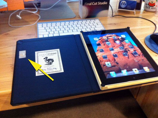
I LOVE my iPad 2. To protect it, I HIGHLY recommend the DODOcase (http://www.dodocase.com/products/dodocase-for-ipad2). My only complaint would be the lack of a magnet in the case to activate/deactivate the iPad through its little magnetic sensor, which is used by other cases, like the foldy-flippy one from Apple (http://www.apple.com/ipad/smart-cover/). What to do? Hack, of course! But, first, I emailed the DODOcase peeps and suggested the feature to them and even sent them links to my source of delicious rare earth magnets, K & J Magnetics (http://www.kjmagnetics.com/). There are thin little rectangular magnets that can easily be embedded into the cardboard cover underneath the backing.

For now, my magnet sits on top of the inside cover:

Magnet added to DODOcase

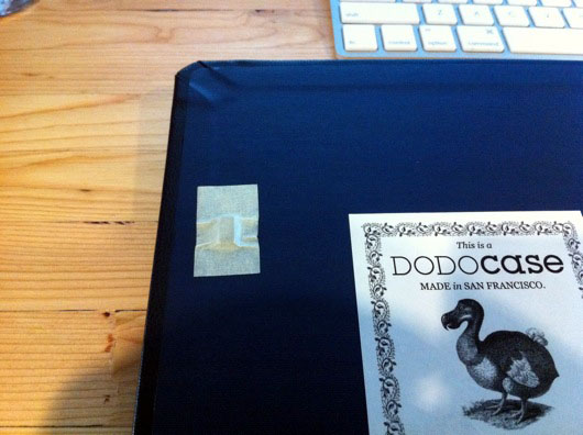
Here is a close-up:

Close-up of magnet on DODOcase for iPad 2

When I have a spare couple of minutes, I'll whip out the X-acto knife and make a neat little compartment for it under the blue liner of the cover.

Hope this helps you other DODOcasers out there!

Desktop Warp Core - The Early Years

Well, we've moved into a new and larger space at the office and we sit at these massive wood and steel desks as teams. Our team decided we needed more "flare" at our desk, so, of course, a big-ass warp core was the first thing that popped into our heads. How hard could that be? The rings of the warp core will be clear-ish fiberglass. The original master, over which we'll make a fiberglass mold for all eight rings, is made of a giant laminated wood block we need to turn on a big lathe.

Laminating 2x6 pieces of pine for the ring master mold

Turns out, I was wrong about Elmer's Wood Glue: It most certainly does stick heartily to plastic tables. My wife wasn't too thrilled about the weird globs of dried glue on the table, right before a big pool party, so I spent a solid half-hour with a wood chisel scraping off those nasty little glue-scabs. Ick and neat at the same time.

Bright White LEDs!

Aside from the general shared engineering tasks, I am in charge of lighting this bad bay. I looked into electroluminescent strips, but it's too expensive and, frankly, not bright enough for our tastes. So, LEDs will be the lighting source of choice on this one. As you can see from the photo above, these inexpensive little 5mm LEDs are plenty bright enough.

The only complaint I have is that they're very directional. At first I thought that I'd just sand them to diffuse the light. But, after some tinkering, I'm going with a sneaky little angled approach: Point the LEDs in a ring at an angle out from the center of the ring so that its light hits the backside of the fiberglass ring in a sorta elongated oval thing. The light from each of the 30 LEDs in a ring will then overlap and make a nice-looking light ring from inside each warp core ring. But, here is my test rig for the LEDs:

LED Test Rig: 4" PVC pipe with foil tape as a reflector

The idea with the LED monster above was to see which worked better for diffusing the LED beams better: Point the LED straight out (left LED), or bend it back toward the reflective foil (right LED) which is convex and should spread the light better. Of course, light dies off over distance and the more we bounce it around, the less of an impact it makes. Below is what the LEDs are projecting without blinding the iPhone camera:

LED beam spread test fire

So, looking at that photo, you see the reflected LED gets a little black spot on the sun today (Sting) in its beam. The other is brighter, but more concentrated. So, we'll see how my idea of pointing the LEDs at the inside of the fiberglass rings at an angle to lengthen the shape of their beams.

I started out by building the microcontroller and MOSFET circuit, complete with firmware that pulses and fades the LEDs. The speed that the rings pulsate into the middle is set by a potentiometer, at the moment. I think I may add the ability for it to try to pulse to the beat of music. Who knows?

Here is the circuit for the LEDs in action:

The microcontroller is my old favorite, the Atmel AVR. This one is an ATmega328P in the PDIP package. The rings of LEDs (in this video, the lines of LEDs) are powered by 12 volts DC and are controlled by N-channel MOSFETs. Each ring will have a total of 30 LEDs. Each ring will have 10 groups of 3 LEDs plus one resistor all run in parallel on the 12-volt rail. Pretty standard stuff.

Expanding foam (40X volume, I seem to recall) to be carved for matter-antimatter combustion chamber

Because of the size of the middle section, the matter-antimatter combustion chamber is quite large in our model, we decided to try making a big round thing of foam and then carving that down to the outside shape of the chamber. We'll then (theoretically) cover it in fiberglass and refine the resulting shell after that.

That's it for this update. I'll get more up here as we progress. Thanks as always for following my blog!